The Pyramid WaveFront Sensor demonstrates significantly greater sensitivity than the Shack-Hartmann sensor when measuring low-order wavefront modes such as tip-tilt, making it more effective for detecting subtle atmospheric distortions in astronomical observations.
Pyramid vs Shack-Hartmann Wavefront Sensors: Sensitivity Gain
Added:Deep Dive
Basic principles of Adaptive Optics (AO) and the role of wavefront sensors in closed-loop control systems.

Adaptive Optics Explained: Wavefront Correction & Microscopy
4.4K
Adaptive optics is an optical technology that corrects wavefront distortions in real-time using a closed-loop system. The complete system includes a collimated laser source, mirrors for beam alignment, lenses for beam sizing, a deformable mirror capable of changing shape to compensate for distortions, and a Shack-Hartmann wavefront sensor with a micro lens array and camera for measuring wavefront aberrations. The system works by first detecting wavefront distortions using the sensor, then calculating the necessary mirror shape changes, and finally applying those corrections through the deformable mirror. This enables applications ranging from astronomical imaging through atmospheric turbulence to biomedical microscopy through scattering tissue samples.
Click to watch →

WEBINAR - A Practical Tour of Adaptive Optics
685
Adaptive optics is a closed-loop system that corrects optical aberrations using three main components: a wavefront sensor to measure distortions, software to calculate correction commands, and a deformable mirror to apply corrections; this technology dramatically improves image quality in applications such as retinal imaging, microscopy, ultra-intense laser systems, and astronomy by compensating for atmospheric turbulence and other optical distortions.
Click to watch →

Claude Plymate on Adaptive Optics - Astronomical League Live - Explore Alliance
203
A typical adaptive optics system operates as a closed servo loop: (1) Light from celestial objects passes through the atmosphere and arrives with distorted wavefronts; (2) The distorted beam reflects off a deformable mirror; (3) A wavefront sensor measures the distortion by analyzing how the wavefront appears; (4) A computer analyzes the measurement and calculates the necessary correction; (5) Amplifiers adjust the deformable mirror to correct the wavefront; (6) The corrected light then produces a diffraction-limited image. The entire cycle must complete faster than atmospheric conditions change to be effective.
Click to watch →
WEBINAR - Adaptive Optics - LIVE DEMO - New Deformable Mirror 'mu DM'
628
Closed-loop operation is recommended when fast aberration update is needed (aberrations changing over time, such as in live animal imaging), when minimizing photobleaching from the AO process itself is important, when fast 3D imaging is required with depth-varying aberrations, and when highest accuracy is needed. For closed-loop systems, high precision wavefront sensors drive efficacy, while high linearity and speed of the wavefront modulator optimize convergence speed. The wavefront sensor must be positioned after the modulator to observe its effect on the wavefront.
Click to watch →

БОЛЬШИЕ наземные телескопы / АКТИВНАЯ и АДАПТИВНАЯ оптика feat @cosmosprosto
37.9K
Adaptive optics systems use wavefront sensors (specifically Shack-Hartmann sensors) to analyze incoming starlight. These sensors consist of arrays of small lenses that form images of a reference star. The computer analyzes these images to determine how the wavefront has been distorted by atmospheric turbulence. Based on this analysis, the system adjusts the mirror shape several times per second to compensate for atmospheric distortions, effectively 'subtracting' atmospheric effects from the observed image.
Click to watch →
Deep Dive
The working mechanism of the Shack-Hartmann Wavefront Sensor, focusing on how lenslet arrays sample the incoming wavefront.

シャック・ハルトマン波面センサ
217
The Shack-Hartmann wavefront sensor is an optical device that measures wavefront distortions by using a lenslet array to sample local wavefront tilts, where each lenslet focuses light onto a sensor array and the displacement of focal spots from their geometric positions indicates the local wavefront gradient; this technology, originally developed from Hartmann's 1900 mask concept and refined by Shack and Hartmann in the 1960s, is widely used for wavefront correction in astronomical telescopes, microscopy, and clinical applications including corneal surgery assessment and inverse Shack-Hartmann systems for measuring ocular aberrations.
Click to watch →
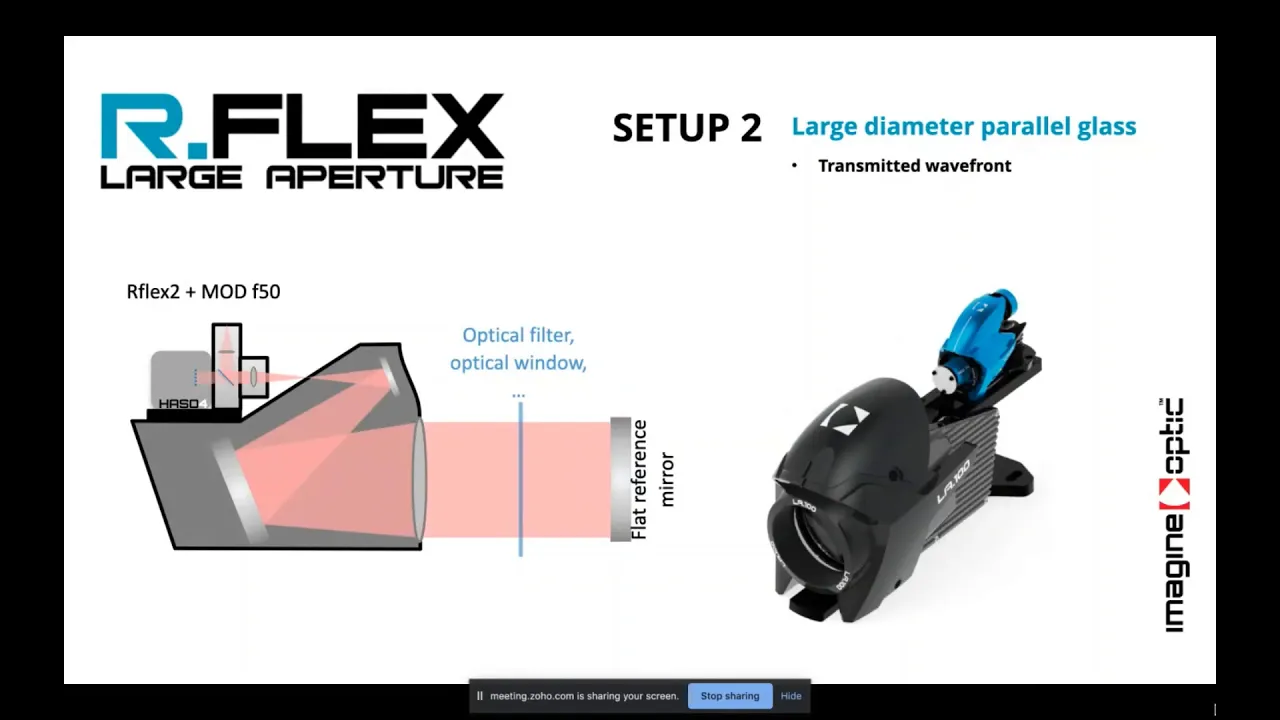
HASO R-FLEX / Webinar Recording: Optical Characterization and Alignment using R-Flex - April 2020
578
The Shack-Hartmann wavefront sensor is a self-contained metrology tool for transmitted wavefront characterization of optical components. It integrates a Shack-Hartmann sensor with an internal light source, enabling measurement of any convergent optical system including camera lenses, telescopes, and microscope objectives. The technology operates across 350-1100nm (VIS) and 900-1600nm (SWIR) wavelength ranges. The sensor uses a micro-lens array positioned approximately 2.5mm from a CCD/CMOS detector. When a flat wavefront enters, each micro-lens creates a spot at its center; aberrations cause spots to shift from ideal positions. By detecting spot centroids (sampled by 5-6 pixels per spot) and calculating local tilt angles through 2D integration, the complete wavefront is reconstructed. This enables absolute measurement of incoming wavefronts without requiring calibration of the optical system under test. The system can simultaneously measure intensity and phase in single acquisitions. Unlike interferometry, it is inherently insensitive to vibration, allowing measurements on ordinary tables.
Click to watch →

Webinar: Presenting VirtualLab Fusion 2021.1
370
Shack-Hartmann sensors measure wavefront curvature by using an array of microlens pairs to focus different parts of an incoming beam onto a detection plane. For a perfectly collimated (planar) wavefront, each microlens focuses its portion of the beam to the same central position. However, when the wavefront has spherical curvature (indicating aberrations), each microlens focuses its portion to a different position offset from the center. The displacement pattern across all microlenses reveals the wavefront's local slope at each point, allowing reconstruction of the overall wavefront shape through inverse analysis of the spot positions.
Click to watch →

PhotoTechEDU Day 22: Measuring, Interpreting and Correcting Optical Aberrations.
6.8K
The Hartmann-Shack sensor measures wavefront aberrations by projecting light through a microlens array onto a CCD camera. Each microlens creates a spot whose position reveals the angle of incoming light rays. By knowing where each lens is located and measuring where each spot appears, the system calculates both ray positions and angles, thereby inferring the complete wavefront shape. Modern ophthalmic sensors use arrays of approximately 1600 tiny spherical lenses to capture detailed aberration information.
Click to watch →

SCHWIND Peramis: Principles and Applications. Webinar | Recording of 14 May 2020
2.8K
Three main wavefront sensor technologies exist: Hartmann-Shack uses lenslet arrays where spot displacements indicate local tilt; Shack-Hartmann provides ~156 points per acquisition; dynamic ray-tracing projects individual rays avoiding overlap but requiring more time. Resolution depends on sampling density—pyramid sensors achieve ~45,000 points versus 250-125 for Hartmann-Shack. Both face dynamic range limitations: Hartmann-Shack cell size affects measurable slope; pyramid sensors saturate when slopes exceed quadrant boundaries. Wavefront maps separate low-order (sphere, cylinder, astigmatism—correctable with spectacles) from high-order aberrations (coma, spherical aberration—requiring laser surgery). Real-time reconstruction at ~30 fps enables accommodation monitoring.
Click to watch →
Deep Dive
Mathematical representation of wavefront optical aberrations, specifically Zernike polynomials and low-order modes like tip and tilt.
Zernike polynomials, aberrations optics part 4 @optometry students
138
Zernike polynomials, developed by mathematician Fritz Zernike in 1934, are mathematical functions that decompose wavefront aberrations into orthogonal components using polar coordinates (ρ, θ), where ρ represents normalized radial distance from the pupil center and θ represents angular position; these polynomials classify optical aberrations by radial order (n) and angular frequency (m), with zero-order representing piston (constant offset), first-order representing tilt, second-order representing clinically significant low-order aberrations (sphere and cylinder correction), and third-order and higher representing high-order aberrations (coma, trefoil, spherical aberration) that cannot be corrected by conventional spectacles but require advanced interventions like custom contact lenses or refractive surgery.
Click to watch →

Polinomio de zernicke - Dra. María Fernanda Opazo Bernal
272
Zernike polynomials are a mathematical framework for describing wavefront aberrations in optical systems, classified into low-order aberrations (myopia, astigmatism, hyperopia, constituting 80-95% of total aberrations) and high-order aberrations (coma, trefoil, spherical aberration, constituting 5-20% of total aberrations). These polynomials are essential for understanding and correcting visual quality issues, with clinical applications in refractive surgery, keratoconus management, and multifocal lens selection. Normal RMS values should be less than 0.04 micrometers, with coma values between 0.025-0.033 micrometers and spherical aberration less than 0.04 micrometers.
Click to watch →

Optical Aberrations Explained: Ray, Wavefront & Zernike
11.2K
Zernike polynomials provide an orthogonal basis for describing wavefront errors on the unit disk, defined by radial index n and angular index m. Lower-order polynomials correspond directly to familiar aberrations: piston (constant), tilt (linear), defocus (quadratic), astigmatism (cubic), coma (cubic), and trefoil (cubic). Unlike Seidel aberrations which depend on both pupil and object coordinates, Zernike polynomials depend only on pupil coordinates, requiring separate coefficients for each object location. Key differences include: Zernike spherical aberration includes an extra defocus term for orthogonality; Zernike astigmatism describes the field exactly between the two focal lines typical of astigmatism. In practice, optical systems are designed with specific tolerances for fabrication errors including decentering, decentration, and tilt. Ray tracing software simulates how these misalignments affect wavefront error, revealing which elements require tighter tolerances. When interpreting coefficients: piston and tilt only shift images laterally (correctable by detector movement); defocus can be corrected by axial movement. Using Fringe indexing, square-numbered indices indicate rotationally symmetric aberrations. Large coefficients at these indices suggest symmetry-breaking errors like lens spacing issues, surface curvature deviations, or material index variations affecting the system.
Click to watch →
Dr Said YAHIAOUI, Aberrometrie: Du Sphero-Cylindre au Pentafoil
154
Wavefronts decompose into Zernike polynomials like musical chords into notes, each with coefficients. The RMS (root mean square) quantifies total aberration. Low-order aberrations (≤2nd order) include defocus, astigmatism, and spherical aberration, correctable by glasses. High-order aberrations (3rd order+) affect peripheral wavefronts and are pupil-dependent. Physiological limits are <0.3-0.35 microns RMS, with asymmetric aberrations being most detrimental.
Click to watch →

What Are Zernike Polynomials? - Optometry Knowledge Base
134
Zernike polynomials are mathematical functions that form an orthogonal basis for describing wavefront aberrations in optical systems, particularly the human eye; they are indexed by radial degree and azimuthal frequency, with lower-order polynomials (radial degree ≤ 2) representing common refractive errors like myopia and astigmatism, while higher-order polynomials (radial degree ≥ 3) characterize complex aberrations such as spherical aberration, coma, and trefoil, enabling precise diagnosis and personalized treatments like wavefront-guided LASIK surgery and specialized contact lenses through technologies like aberrometers.
Click to watch →
Deep Dive
Concepts of optical detection limits, including signal-to-noise ratio (SNR) and photon noise in detectors.

Optical Final
116
Optical detectors face thermal noise (Johnson noise), dark current noise, and shot noise. The signal-to-noise ratio (SNR) determines minimum detectable power. The quantum limit represents the fundamental minimum optical power required for detection, determined by the quantum nature of light. At the quantum limit, SNR is limited by the shot noise of the signal itself. The minimum detectable power is Pmin = hν/η, where η is quantum efficiency.
Click to watch →

201412051900 A csillagászati képrögzítés alapjai
1.3K
The signal-to-noise ratio (SNR) is calculated as the signal divided by the square root of the total noise. The signal includes both the astronomical object and its inherent photon noise. The total noise includes photon noise (proportional to the square root of the signal) and readout noise (constant per readout). A good SNR of 50 or higher is needed for quality astronomical images. Photon noise is an inherent statistical variation in the arrival of photons from astronomical objects, where even with a constant average photon rate, the actual number of photons arriving in any given time interval varies randomly.
Click to watch →
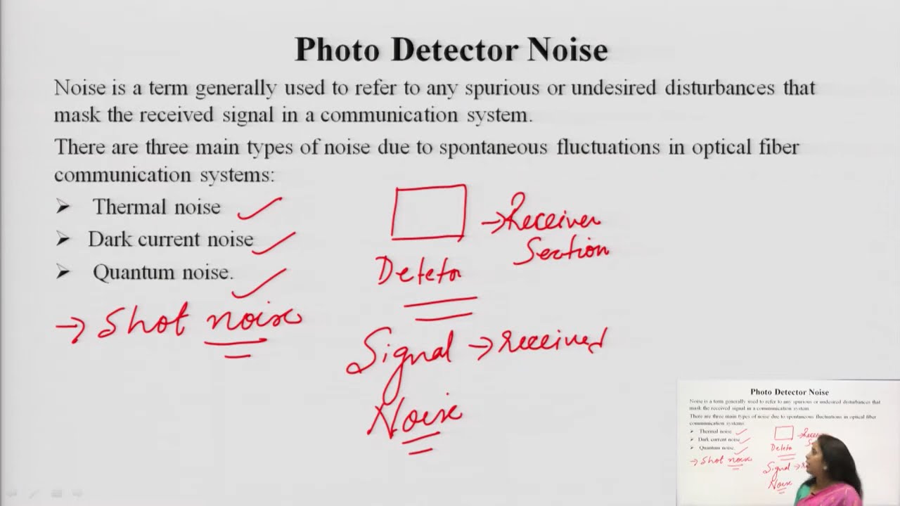
Photo Detector Noise and SNR
13.5K
In optical communication systems, photo detectors face four main noise sources: thermal noise (from electron-ion interactions in conductors, I²̄ = 4kTB/R), dark current noise (from residual current without optical input, I²̄ = 2eIDB), shot noise (from random photo-carrier generation, I²̄ = 2eIPB), and quantum noise (from photon arrival statistics following Poisson distribution). The Signal-to-Noise Ratio (SNR) is calculated as SNR = IP² / (Ishot² + Ithermal² + Iamplifier²), where IP is the photocurrent and the denominator includes all noise contributions. Comparing PIN and APD photo detectors, PIN offers lower noise and faster response time but lower sensitivity, while APD provides higher sensitivity through avalanche multiplication but exhibits higher noise levels and poorer temperature stability.
Click to watch →

Photodetector Noise
13K
Photo detectors in optical communication systems generate four main types of noise: quantum noise (shot noise) due to statistical photoelectron production, bulk dark current noise from thermally generated carriers in the pn junction, surface leakage current noise from surface defects, and thermal noise from circuit resistances. The signal-to-noise ratio (SNR) is calculated as the ratio of signal power (from photo current) to total noise power (sum of all noise sources). For avalanche photodiodes, the optimal multiplication factor M that maximizes SNR is determined by differentiating the SNR expression with respect to M and equating it to zero, yielding M^(x+2) = [2q(Rs + Ra) + 4kBT/RL] / [xq(Ip + Id)], where quantum and dark current noises are multiplied by M² × Fm (multiplication factor and figure of merit), while surface leakage current remains unaffected by gain.
Click to watch →

Signal to Noise Ratio
24.8K
Signal-to-noise ratio (SNR) is a critical property of microscope images that determines the ability to detect dim samples, measure intensity accurately, and achieve high resolution; SNR is fundamentally limited by Poisson noise (which scales with the square root of photon count) and detector noise (read noise, dark noise, and multiplicative noise), and can be improved by collecting more signal through optimal fluorophore selection, matched filter sets, high numerical aperture objectives, appropriate imaging modalities, and efficient detectors, while simultaneously reducing noise through background minimization, proper illumination control, and cooled cameras with low read noise.
Click to watch →
Prerequisite Knowledge
- Concept 01Basic principles of Adaptive Optics (AO) and the role of wavefront sensors in closed-loop control systems.
- Concept 02The working mechanism of the Shack-Hartmann Wavefront Sensor, focusing on how lenslet arrays sample the incoming wavefront.
- Concept 03Mathematical representation of wavefront optical aberrations, specifically Zernike polynomials and low-order modes like tip and tilt.
- Concept 04Concepts of optical detection limits, including signal-to-noise ratio (SNR) and photon noise in detectors.
Subsequent Learning
- Step 01Dynamic modulation techniques in Pyramid Wavefront Sensors to optimize the trade-off between sensitivity and dynamic range.
- Step 02Implementation and performance of Pyramid Wavefront Sensors in next-generation Extremely Large Telescopes (ELTs) and Extreme Adaptive Optics (ExAO).
- Step 03Advanced wavefront reconstruction algorithms and handling of non-linearities specific to pyramid sensors.
- Step 04A comparative study of alternative wavefront sensing architectures, such as Curvature sensors and Fourier-transform wavefront sensors.
Start
Signal
Deepen
Climax
Pivot
Detail
Apply
Result
Close
Start
0:29Playing Section
- 1
Opening moments establishing the video's setting.
- 2
Initial audio cues set the tone for the content.
- 3
Brief visual or sound introduction begins.
Modulation and Dynamic Range Trade-offs in Pyramid Wavefront Sensing
While the Pyramid Wavefront Sensor (PWFS) theoretically outperforms the Shack-Hartmann Wavefront Sensor (SHWFS) in sensitivity—especially for low-order modes like tip-tilt—this gain is highly contingent on closed-loop conditions. The PWFS suffers from a narrow dynamic range and severe non-linearity. To mitigate this, physical modulation of the light beam is required, which directly reduces the PWFS's sensitivity gain, bringing its performance closer to that of the SHWFS. Additionally, the 'optical gain' of the PWFS is highly sensitive to residual wavefront errors and atmospheric seeing, demanding complex real-time calibration. In contrast, the SHWFS offers a much larger dynamic range, excellent linearity, and a stable calibration matrix, making it far more robust in open-loop operations, poor seeing conditions, or initial acquisition phases.
Deep Dive
Dynamic modulation techniques in Pyramid Wavefront Sensors to optimize the trade-off between sensitivity and dynamic range.
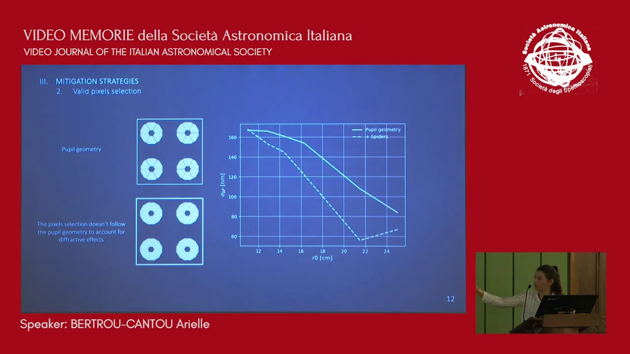
Modulation strategies to mitigate island effect with the pyramid wavefront sensor
196
The island effect in Extremely Large Telescopes (ELTs) occurs when spider support structures break wavefront continuity, causing differential piston between sub-apertures that severely degrades image quality; pyramid wavefront sensors face challenges because they cannot simultaneously sense differential piston and other modes effectively, and while modulation strategies like clover and Annie podtrekker can improve sensing, there is no optimal solution, with increasing wavelength being the most effective mitigation strategy.
Click to watch →

Episode #111 - Adapting your Optics w/ Jacob Taylor
331
The pyramid wavefront sensor works by pushing light across all four facets of an optical pyramid, creating four images. The non-linearity comes from the fact that if light is only in one facet, you have no information about changes in other facets. To mitigate this, modulation is used - rotating the pyramid rapidly around each face so light is always in all four facets. This makes it linear but less sensitive, requiring a larger tip to achieve circular illumination. Earth's atmosphere has a known turbulence profile that follows a specific pattern. The atmosphere can be thought of as a bunch of tiny lenses stacked on top of each other with different sizes. Most turbulence is large-scale, with the predominant effect being 'tip and tilt' (which moves the spot on the camera plane). For the lowest-order aberrations (tip and tilt, focus), you don't need a fancy wavefront sensor. Tip and tilt can be corrected by watching star position and using a control loop to keep the star centered.
Click to watch →

Wavefront-Guided Individualized Vision Correction For Keratoconus And Presbyopia
623
Wavefront sensor design involves critical trade-offs between sensitivity and dynamic range. Sensitivity refers to the smallest magnitude of aberration that can be detected, while dynamic range indicates the maximum aberration magnitude measurable without error. Longer focal length lenslets provide better sensitivity (smaller displacements are detectable) but reduce dynamic range (spots may overlap). Shorter focal lengths increase dynamic range but decrease sensitivity. Smaller lenslets improve spatial resolution but reduce dynamic range. Optimal design requires balancing these factors based on clinical requirements.
Click to watch →

Wavefront Sensing and Control Basics for Telescopes
272
This extensive section covers the complete landscape of wavefront sensing technologies used in astronomical adaptive optics. It begins with Shack-Hartmann sensors, explaining how lenslet arrays in the pupil plane create spot patterns whose centroids reveal wavefront slopes, with detailed analysis of the mathematical relationship between spot displacement and wavefront slope. The section addresses fundamental trade-offs between dynamic range and sensitivity, including saturation effects when spot displacement exceeds spot radius. It then advances to pyramid wavefront sensors, which divide focal plane PSFs into four quadrants using pyramid masks, and Zernike phase mask sensors that create interference patterns for high-sensitivity piston measurements. Throughout, the section emphasizes how each technology balances competing requirements of resolution, sensitivity, dynamic range, and photon efficiency.
Click to watch →

Jeffrey Chilcote: GPI 2.0: Revealing Exoplanets through High-Contrast Imaging
121
GPI 2.0 replaces the Shack-Hartmann wavefront sensor with a pyramid wavefront sensor based on designs from NEAT/TMT. This upgrade increases operating speed from 1 kHz to 2 kHz and uses a zero-read-noise EMCCD (CCD 220) from Newwood Cameras instead of the original First Light CCD. Simulations show this should enable operation to 13th magnitude while gracefully degrading to 14th magnitude, with potential operation to 15th magnitude under good conditions.
Click to watch →
Deep Dive
Implementation and performance of Pyramid Wavefront Sensors in next-generation Extremely Large Telescopes (ELTs) and Extreme Adaptive Optics (ExAO).
БОЛЬШИЕ наземные телескопы / АКТИВНАЯ и АДАПТИВНАЯ оптика feat @cosmosprosto
37.9K
Adaptive optics systems use wavefront sensors (specifically Shack-Hartmann sensors) to analyze incoming starlight. These sensors consist of arrays of small lenses that form images of a reference star. The computer analyzes these images to determine how the wavefront has been distorted by atmospheric turbulence. Based on this analysis, the system adjusts the mirror shape several times per second to compensate for atmospheric distortions, effectively 'subtracting' atmospheric effects from the observed image.
Click to watch →

САМЫЙ БОЛЬШОЙ наземный телескоп в истории - ELT
49.9K
Adaptive optics compensates for atmospheric distortions by deforming a mirror under computer control, producing images nearly as sharp as space-based observatories. The system requires reference stars, with eight lasers creating artificial stars by exciting sodium atoms in the upper atmosphere. Wavefront cameras (ELVIS, LISA, FReD) continuously monitor distortions and transmit data for real-time correction. The MORFEO module uses two additional deformable mirrors to build 3D atmospheric distortion maps across three height slices, enabling correction at multiple atmospheric layers simultaneously.
Click to watch →

PSW 2452 Extreme Adaptive Optics | Olivier Guyon
1.8K
Extreme adaptive optics (XAO) pushes AO to deliver diffraction-limited performance over narrow fields for exoplanet imaging. Unlike conventional AO targeting wide fields, XAO sacrifices coverage for ultimate correction quality. The Subaru XAO system demonstrates this: an 8-meter telescope beam compressed to ~1 cm, featuring a 20mm deformable mirror with 2000 actuators at 10 kHz, gold-coated infrared optics, and multiple optical wheels for coronagraph selection. Three key requirements define XAO: operation above 2 kHz to track rapidly changing turbulence, large numbers of control modes requiring many actuators and sensor pixels, and high measurement accuracy. Mathematical foundations rely on linear relationships between sensor measurements and mirror commands, with control matrices derived via Singular Value Decomposition. Pyramid wavefront sensors split light into four images using a glass pyramid, measuring aberrations by analyzing intensity distributions. Wavelength selection balances measurement sensitivity against photon availability for different star types. The system achieves diffraction-limited performance shown by Airy rings around star images, demonstrating the power of XAO combined with coronagraphy for exoplanet detection.
Click to watch →
Jeffrey Chilcote: GPI 2.0: Revealing Exoplanets through High-Contrast Imaging
121
GPI 2.0 replaces the Shack-Hartmann wavefront sensor with a pyramid wavefront sensor based on designs from NEAT/TMT. This upgrade increases operating speed from 1 kHz to 2 kHz and uses a zero-read-noise EMCCD (CCD 220) from Newwood Cameras instead of the original First Light CCD. Simulations show this should enable operation to 13th magnitude while gracefully degrading to 14th magnitude, with potential operation to 15th magnitude under good conditions.
Click to watch →

IfA Colloquium - Dr. Olivier Guyon - The Path to Direct Imaging and Spectroscopy of Habitable Exo...
280
The pyramid wavefront sensor measures optical aberrations by splitting focused starlight into four beams using a transmissive pyramid located at the diffraction spot. The distribution of light between these four beams reveals information about wavefront errors. This sensor operates at kilohertz speeds (up to 3.5 kHz) and can correct over 1,200 optical modes simultaneously, enabling real-time adaptive optics correction that maintains diffraction-limited performance even in visible wavelengths.
Click to watch →
Deep Dive
Advanced wavefront reconstruction algorithms and handling of non-linearities specific to pyramid sensors.

WFS Workshop 2021 Day1 Session 1 :: Wavefront Sensing 1
615
This session presents two complementary approaches to wavefront reconstruction in adaptive optics. The first approach, moving horizon estimation, addresses the phase retrieval ambiguity problem by incorporating temporal information from multiple wavefront sensor images and deformable mirror shapes. Using higher-order Taylor expansions and maximum likelihood estimation, this non-linear method successfully identified segment piston errors in the Giant Magellan Telescope, improving Strehl ratio from 30-50% to 60%+. The second approach presents a universal non-linear reconstruction method using Landweber iteration that works across all Fourier-type sensors (pyramids, Shack-Hartmann, Zernike) by simply changing the optical transfer function input. This method automatically compensates for optical gain approximations inherent in linear methods. Both approaches represent significant advances over traditional linear reconstruction methods, though they require substantial computational resources and careful mathematical formulation.
Click to watch →
Episode #111 - Adapting your Optics w/ Jacob Taylor
331
The pyramid wavefront sensor works by pushing light across all four facets of an optical pyramid, creating four images. The non-linearity comes from the fact that if light is only in one facet, you have no information about changes in other facets. To mitigate this, modulation is used - rotating the pyramid rapidly around each face so light is always in all four facets. This makes it linear but less sensitive, requiring a larger tip to achieve circular illumination. Earth's atmosphere has a known turbulence profile that follows a specific pattern. The atmosphere can be thought of as a bunch of tiny lenses stacked on top of each other with different sizes. Most turbulence is large-scale, with the predominant effect being 'tip and tilt' (which moves the spot on the camera plane). For the lowest-order aberrations (tip and tilt, focus), you don't need a fancy wavefront sensor. Tip and tilt can be corrected by watching star position and using a control loop to keep the star centered.
Click to watch →
Dr Said YAHIAOUI, Aberrometrie: Du Sphero-Cylindre au Pentafoil
154
Wavefront sensing reconstructs 3D wavefronts from distortion analysis. Outgoing systems use lasers on the retina with microlens arrays (Shack-Hartmann), limited by lens count and crossover errors. Entry systems project lasers onto the retina and photograph distortions, avoiding crossover but potentially missing points. Modern systems like iPro use pyramidal mirrors for 45,000 points, while iTrace uses sequential slit scanning. All use safe infrared or green lasers. Wavefronts decompose into Zernike polynomials like musical chords into notes, each with coefficients. The RMS (root mean square) quantifies total aberration. Low-order aberrations (≤2nd order) include defocus, astigmatism, and spherical aberration, correctable by glasses. High-order aberrations (3rd order+) affect peripheral wavefronts and are pupil-dependent. Physiological limits are <0.3-0.35 microns RMS, with asymmetric aberrations being most detrimental.
Click to watch →

Benjamin Gerard: Developing New Adaptive Optics Wavefront Sensing Technologies for WMKO
143
Two innovative wavefront sensing approaches are demonstrated. The Pupil Plane Tilt method uses a deformable mirror to create intentional local tilt shapes, producing characteristic PSF distortions. Alternating between tilted and flat mirror states with two captured images resolves phase ambiguities. This broadly applicable technique works for any PSF-imaging scenario including solar system science and laser guide stars. The Bright Pyramid sensor adds a λ/2 piston phase shift to the conventional four-sided pyramid, diffracting more light into pupil footprints. Laboratory testing confirms improved linearity in reconstructing known Zernike modes, demonstrating enhanced performance for second-stage correction applications.
Click to watch →
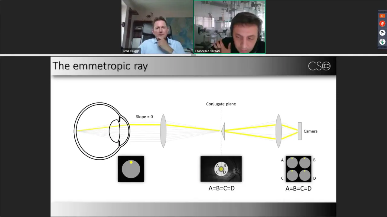
SCHWIND Peramis Principles and Applications Webinar Recording of 14 May 2020
638
Optical aberration describes deviations from ideal light focusing, causing light rays to spread across the retina instead of converging at a single point. A wavefront represents surfaces of constant optical phase, always perpendicular to light rays. Wavefront error quantifies the difference between actual and ideal wavefronts. The principle of light reversibility enables wavefront sensing by analyzing exit paths. The pyramidal sensor uses two conjugate planes: one imaging the retina and another imaging the pupil. Light exiting the eye creates four pupil images (sub-pupils) in the second plane. Rays with zero slope split energy equally among all four sub-pupils, while tilted rays create asymmetric intensity distributions. These intensity variations correlate directly with wavefront slope, enabling calculation of partial derivatives along x and y axes. Integration reconstructs the complete wavefront. This technology achieves 45,000 sampling points versus ~125-250 for Hartmann-Shack sensors, enabling real-time 30 fps reconstruction without complex fitting algorithms.
Click to watch →
Deep Dive
A comparative study of alternative wavefront sensing architectures, such as Curvature sensors and Fourier-transform wavefront sensors.
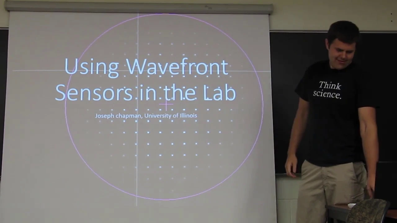
Wavefront Sensor Tutorial: Zernike Polynomials & Software
7.7K
Wavefront sensors use mathematical decomposition via Zernike polynomials to characterize optical beam quality by measuring wavefront aberrations such as tip, tilt, focus, and spherical aberration; two primary technologies exist—Hartmann-Shack sensors that use micro-lens arrays to create focus spots whose centroid displacements reveal wavefront shape, and quadtree wavefront sensors that employ diffraction gratings to generate four displaced beam copies analyzed through Fourier transform for wavefront reconstruction.
Click to watch →

Adaptive Optics
476
The curvature sensor measures wavefront aberrations by comparing intensity distributions in two different planes separated by a known distance. A beamsplitter directs light to two separate channels. Converging wavefront sections show reduced intensity in one channel compared to the other, while diverging sections show increased intensity. The difference between these intensity measurements reveals information about local wavefront curvature, enabling reconstruction of the overall wavefront shape.
Click to watch →

QWLSI Wavefront Sensors for Tomorrow’s Challenges in Optics Metrology - OIDA Technology Showcase -
801
Three major wavefront sensing technologies exist: Fizeau interferometry, Shack-Hartmann sensors, and quadri-wave lateral shearing interferometry. Key comparisons include: (1) Compactness - all wavefront sensors are camera-like devices, more compact than bulky interferometers; (2) Sampling capabilities - megapixel cameras provide excellent sampling, with quadri-wave offering superior capabilities compared to Shack-Hartmann; (3) Achromaticity - quadri-wave is the only truly intrinsically achromatic technology by design, unlike Shack-Hartmann which requires post-processing tricks and Fizeau which has built-in laser sources requiring separate interferometers per wavelength; (4) Vibration sensitivity - quadri-wave cameras are self-referenced and less sensitive to vibrations compared to phase-shifting interferometers; (5) Dynamic range - quadri-wave can measure up to 500 micron peak-to-valley wavefront distortions across UV to long-wave infrared wavelengths.
Click to watch →
Wavefront Sensing and Control Basics for Telescopes
272
This extensive section covers the complete landscape of wavefront sensing technologies used in astronomical adaptive optics. It begins with Shack-Hartmann sensors, explaining how lenslet arrays in the pupil plane create spot patterns whose centroids reveal wavefront slopes, with detailed analysis of the mathematical relationship between spot displacement and wavefront slope. The section addresses fundamental trade-offs between dynamic range and sensitivity, including saturation effects when spot displacement exceeds spot radius. It then advances to pyramid wavefront sensors, which divide focal plane PSFs into four quadrants using pyramid masks, and Zernike phase mask sensors that create interference patterns for high-sensitivity piston measurements. Throughout, the section emphasizes how each technology balances competing requirements of resolution, sensitivity, dynamic range, and photon efficiency.
Click to watch →
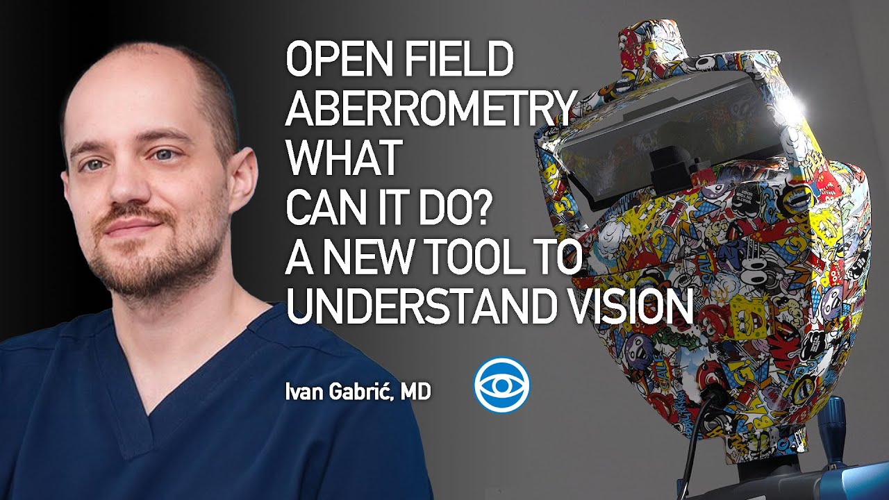
OPEN FIELD ABERROMETRY WHAT CAN IT DO? A NEW TOOL TO UNDERSTAND VISION - Ivan Gabrié, MD
272
Different wavefront sensors offer varying resolution capabilities: Hartmann-Shack sensors provide 1-300 points over a 6mm pupil, while pyramid sensors like those in the OSIRIS T offer approximately 5,800 points across a 9mm pupil. The OPFA device provides even higher resolution with over 5,800 points in the central 3mm zone, nearly tripling the resolution of competing devices in the most critical area for vision. Higher resolution enables detection of finer corneal irregularities that lower-resolution systems miss.
Click to watch →
Start
Signal
Deepen
Climax
Pivot
Detail
Apply
Result
Close
Start
0:29- 1
Opening moments establishing the video's setting.
- 2
Initial audio cues set the tone for the content.
- 3
Brief visual or sound introduction begins.
Modulation and Dynamic Range Trade-offs in Pyramid Wavefront Sensing
While the Pyramid Wavefront Sensor (PWFS) theoretically outperforms the Shack-Hartmann Wavefront Sensor (SHWFS) in sensitivity—especially for low-order modes like tip-tilt—this gain is highly contingent on closed-loop conditions. The PWFS suffers from a narrow dynamic range and severe non-linearity. To mitigate this, physical modulation of the light beam is required, which directly reduces the PWFS's sensitivity gain, bringing its performance closer to that of the SHWFS. Additionally, the 'optical gain' of the PWFS is highly sensitive to residual wavefront errors and atmospheric seeing, demanding complex real-time calibration. In contrast, the SHWFS offers a much larger dynamic range, excellent linearity, and a stable calibration matrix, making it far more robust in open-loop operations, poor seeing conditions, or initial acquisition phases.
Basic principles of Adaptive Optics (AO) and the role of wavefront sensors in closed-loop control systems.
The working mechanism of the Shack-Hartmann Wavefront Sensor, focusing on how lenslet arrays sample the incoming wavefront.
Mathematical representation of wavefront optical aberrations, specifically Zernike polynomials and low-order modes like tip and tilt.
Concepts of optical detection limits, including signal-to-noise ratio (SNR) and photon noise in detectors.
Dynamic modulation techniques in Pyramid Wavefront Sensors to optimize the trade-off between sensitivity and dynamic range.
Implementation and performance of Pyramid Wavefront Sensors in next-generation Extremely Large Telescopes (ELTs) and Extreme Adaptive Optics (ExAO).
Advanced wavefront reconstruction algorithms and handling of non-linearities specific to pyramid sensors.
A comparative study of alternative wavefront sensing architectures, such as Curvature sensors and Fourier-transform wavefront sensors.
6.9K views65likes4:14@PadovAdOptOriginal Release: 2012-03-06
sh oh oh oh he w n oh a
Up Next
43:42
Wavefront Sensing and Control Basics for Telescopes
@SaganSummerWorkshop
272 views•2024-07-24

12:53
21cm Hyperfine Transition in Neutral Hydrogen: Radio Astronomy Basics
@AaronRobertParsons
12.4K views•2011-10-13

32:32
NMR Spin Physics I: Zeeman Effect, Resonance Condition & Larmor Frequency
@nptel-indianinstituteofsci8064
2.3K views•2024-01-17

27:14
Entropy and the Second Law of Thermodynamics Explained
@veritasium
27.5M views•2023-07-01
Related Study Plans & Knowledge Roadmaps
Structured learning paths in Physics
physics
Nuclear Physics (Decay, Fission & Reactors)
01Atomic Structure and the Binding Force
02Radioactive Decay and Half-Life
03Nuclear Fission Mechanics and Chain Reactions
+ 2 more learning modules
12h5 modules
Explore Roadmap
physics
Soft Matter (Polymers, Colloids & Rheology)
01Foundations of Soft Matter & Thermal Forces
02Polymer Physics and Macromolecules
03Colloids, Surfactants, and Self-Assembly
+ 2 more learning modules
38h5 modules
Explore Roadmap
physics
Analytical Mechanics: Lagrangian & Hamiltonian
01Mathematical Foundations: Calculus of Variations
02From Newtonian Mechanics to Constraint Dynamics
03The Principle of Least Action & Lagrangian Mechanics
+ 3 more learning modules
28h6 modules
Explore Roadmap
physics
General Relativity (Spacetime & Cosmology)
01Foundations of Relativity: Special Relativity
02The Geometry of Spacetime: Equivalence Principle & Curvature
03Einstein's Field Equations: The Mathematics of Gravity
+ 2 more learning modules
55h5 modules
Explore Roadmap