








![[사마귀 자동제어 문제풀이] 19. 피드백 분석](https://i.ytimg.com/vi/DQD4UiHMDTo/maxresdefault.jpg)








This video demonstrates how to set up and operate an adaptive optics system using the AOS software, covering hardware requirements (wavefront sensor, drive electronics, deformable mirror), software configuration (camera selection, AOIS setup, control matrix creation), and the complete process of closing an adaptive optics loop including actuator connection, control matrix generation, and real-time wavefront correction with adjustable parameters like gain and settle time.
AOS Adaptive Optics System and Software Setup Tutorial
Added:Basic principles of wave optics, specifically wavefront aberrations, phase distortion, and optical path differences.
Fundamental understanding of wavefront sensing technologies, such as the Shack-Hartmann wavefront sensor.
Working principles of active optical components, particularly deformable mirrors (DMs) and their actuators.
Core concepts of feedback control systems, including error signals, loop gain, and closed-loop operation.
Advanced control algorithms for adaptive optics, including modal control, predictive control, and sensorless AO.
Application of adaptive optics in astronomical observation, such as Laser Guide Star (LGS) systems and multi-conjugate AO.
Utilization of adaptive optics in biomedical imaging, particularly in high-resolution retinal imaging and deep-tissue microscopy.
Performance characterization and optimization of AO systems, focusing on metrics like the Strehl ratio and correction bandwidth.
674 views5likes12:55Original Release: 2017-01-02
Hi, my name is Justin Manel. I'm with Active Optical Systems and this is a video describing how to use the AOS adaptive optics software to close an adaptive optics loop.
I'll start with some setup prerequisites, then talk about our optical setup, and then describe how to use the software.
To get the software, you can go to the AOS SharePoint site at sp.aosshylc.com/ aos-lc.com/sites/portal.
Make sure you use https as the the prefix to this in order to enable the security settings. Then you can go to downloads export control software and I usually go to the current version and download one of the most current versions of this and install the software.
You'll need to then have an AOS wavefront sensor attached. Uh this is showing a gig version. If you're using a gig version, you'll need something that will inject power onto the PoE line if it's a PoE wavefront sensor. These TPLink PoE injectors is what we've been using for that. In the lab here, you'll need the AOS key software installed, which is nominally installed.
Um and you'll need an AO licensed key for this. Um, the key lock software is installed as part of the AOS installer.
Then you'll need to plug that key into a USB port.
You'll need to have a set of drive electronics set up to run this. Uh, this is one of our newer versions of electronics that has um 32 channels of output. Um, it has a an LVDS port here.
U, we're going to be demonstrating this today with the gig e port. Um, the software that we have now doesn't have the ability to address LVDS. That's coming soon. Um, and you'll have to have power plugged in. You'll have to have it turned on. Um, and then you'll have to have the Ethernet um, plugged directly into uh, a network interface card or nick into the computer. Um, you can use a USB to uh, giggy adapter for that. Uh, and I'm using that during today's demo.
This is the optical setup we have for this. Um, I have a laser that is um, expanded up. This is an ND filter, but expanded up um, through this lens here and this lens um, bounced off of a DM uh, and then put down into a wavefront sensor here uh, for the demo. That's all you need to close an AO loop. It fits onto a very small little breadboard.
Uh, now on to the software.
Okay, so now I'm loading up the AOS software.
This is the splash screen for that. And while it's running the splash screen, it's going off and uh checking for various interfaces and seeing what hardware it has attached. Specifically, it's starting with the camera hardware.
Um it brings up the wavefront slopes, image alignment, and zernick bar charts.
And here we go. uh is the main this is the main window for the software.
I am first going to rearrange the windows here um so I can see what's going on a little better.
Now I can choose a camera and so um it has uh built into the AOS software is a bunch of different camera options uh including the Vision Research Phantom cameras. Um, you can use a camera link camera if you have a National Instruments uh frame grabber card. And uh here is the Vima Makeo camera that we're going to be using for this demo today.
So, it's connecting to the camera, getting it all set up, and now I can grab a frame from it. Um, I've already gone through and created a set of of um AOIS for this, but let me turn those off so you can see the image. Um, this image is a little warped beyond what I'd like uh due to the fact that I'm using a very short focal length uh lens in the system that's causing a lot of spherical aberration, but we can still use it. Um, and you can see the AOIS here. I've also got a piece of dust in here that I've just eliminated um from consideration by eliminating some of the AOIS up here.
Okay, so now um I can tell it that this is the nominal flat. I can I can also load a flat here, but I'm just going to tell it that this is nominal flat.
And this will um I can do that by without changing the AOIS. I can if I wanted to change the AIS, I can hit create reference, but I'm just going to have it recenter the spots inside the AOIS and tell it that that's flat. And now we're just measuring noise in the system. I'm going to switch this to 2D plot so I can see better what's going on. Um there we go. Okay. So yeah, we're seeing, you know, 50 nanometers of noise or something like that. Okay. Uh next, I'm going to start up the adaptive optics portion. Again, you have to have an adaptive optics key in order to do this. These are the actuators uh the actuator pattern on the DM that I have.
And I need to connect then to the drive electronics. So I go to configuration, change from simulated DM to network DM, click on device settings, and say find devices. This will go off to each of the nicks and uh send a UDP packet out um and find on our uh any basically any network throughout the the computer um where the um uh different drive electronics are. So, in another lab down the hall, we have a drive electronics um on this IP address. Since I have this one directly plugged in, it is giving me a 169 address. I can then say use device, which will copy this information up to here and then connect.
Now, it's connected. I can just say okay and move this out of the way.
Um to make sure that I'm really connected, what I can do is um go to DM control increment voltage. I set this set set this to 1%. And go to continuous acquire and start poking on actuators.
There's an actuator. There's another actuator.
There we go. This looks good. Okay. So, I'm seeing the actuators in the DM.
That's great. Okay. I'll hit stop here.
Um, next thing I want to do in order to do wavefront sensor based adaptive optics is create uh a control matrix or load a control matrix. Today I'm going to create one. And so I'm going to tell it to bias the mirror up to 5%. Um, and poke 5%. And I'm going to tell it to poke up down and make sure it grabs a clear frame buffer. So, uh, grabs an extra frame to clear the buffer. I can click this button here, and it will go through and, um, poke the actuators. It's hard to see right now because I'm poking so lightly.
Um, but you could, if you were watching carefully, this this plot was changing.
And then it goes through and generates for me the uh, AO plotforms uh, plots.
And so, this is the SVD gains. And so, you can see I've got um, pretty uh, narrow range except for this last one.
Uh, so I will probably go through and make sure I have Yep. One mode removed.
Good. So, it'll remove that mode for me.
Um, these are the wave sensor modes that it found.
And let's just jump all the way to the end here and take a look at what that last mode was. Yeah, it looks like I've got noise out here. So, it was removing like a noise mode here. That's okay. Um, DM modes, you can take a look at those.
And so, um, there's probably all kinds of flips and twists. By the way, you can you can accommodate those if you know about them, uh, with the, uh, flip on, read, and rotate options, uh, on the DM controller.
This is the let's start with this. This is the poke matrix that measured um, this is then the control matrix.
Okay, that makes sense. Uh, this is a very important plot to take a look at.
This is the influence function amplitude. So, it's measuring influence function amplitudes that are significantly above the RMS noise floor that it's measuring. Uh, that means we're getting good measurements of all of our influence functions. So, this all looks pretty good. I've got a decent looking control matrix and now I'm ready to do some adaptive optics.
So, I have to have something to to compensate though. Um, so I'm going to um stop here, have it recenter the spots at this bias condition. Um, so now I'm seeing basically noise and I'm going to tell it to increment the voltage on a few of these actuators.
Okay, so I've got three actuators that are looking funny here. And now I can go down here and specify um the AO parameters. So specifically I'll start with gain. I'll set that at 70%. Uh I'm not going to use hysteresus compensation uh for this. Hysteresus compensation drives the actuators to zero between each application of the of the voltages.
Uh this helps compensate some of the hysteresus in the actuators. Um, this is really useful if you're trying to get back to a a flat state where uh you've compensated that hysteresus. Um, I'm going to remove average tilt. Uh, I'm going to tell it not to bias the DM so I can, you know, keep it in this kind of state. I'm going to change this to uh autoscale plotting this so I can see a little better the uh actuators I've hit.
And it looks, by the way, that like I do have uh a a rotate or a uh like a 180 degree rotation on the the um orientation of the DM here. Um let's see. I'm going to have 100% leak factor, so there's not going to be any leak. Um I'm going to let 10 milliseconds of of time elapse between the application of a command in the software and the readout of a next um frame from the wavefront sensor.
And I'm ready to go. So, I'm going to start by just doing 100 iterations. Um, and uh, you know what? Let's slow this down for the video. Let's make this, oh, I don't know, say 500. Okay. And say arm and trigger. And what's going to happen here for the video here, it's going to try to get the DM back into a good position here. Um, if you set this up to do 100 iterations, it will sit there and do 100 iterations. Uh, since we've now converged the DM back to a decent position, it's not really moving all that much anymore. Uh, I will pause the video here so you don't have to watch the rest of this.
Okay, so we're back and it converged to a state. Let's see what it looks like now. Yeah, basically it converged back into a what amounts to noise here. So, um, we're seeing, you know, seven nanometers peak to valley on this. This is great. it it did a great job of getting it back to where it was.
Um, it did dip these down a little bit and this is a hysteresus phenomenon. Uh, so that the actuators that were activated are a little bit lower than the rest of them. It also because I removed the average tilt uh left a tilt term residual onto this. Um, and that's okay if you've got a control system uh uh somewhere else in the system that's fixing that. You may want to let the DM fix it if it's if you're not expecting a tremendous amount of tilt. Um, so to demonstrate the speed in all of this, I'm going to bring that back to, you know, 10 milliseconds of settle time.
And I'm going to do a continuous start here. And it's going to basically be running um as fast as it can. And it's done with 100 iterations here. Um, I just stopped it. I got close. 99. Great.
And let's see where we are. Where we are.
Okay, it did a pretty good job here of of doing it, but not perfect. So, let's see if I can leave this on and try again. I'm going to bring this to just 10 iterations. Arm and trigger.
There we go. It finished 10.
There we go. Now, we're back to to a decent looking position here. Uh, this is now 90 peak to valley. A little worse than it was, uh, but not terrible.
Okay, so this is how you go through and set up a wavefront sensor and DM uh configuration and run adaptive optics in the AOS software. Thank you very much for listening.
Up Next

9:00
ACE Matlab Toolbox Tutorial: A Comprehensive Guide to Adaptive Optics
@adaptiveoptics
1.3K views•2015-03-27

12:54
Triumph of Orthodoxy Icon: Byzantine Art & History Explained
@BenCallan
2.1K views•2024-08-06
17:16
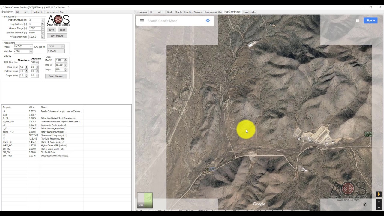
Beam Control Scaling Law & Control Simulator Tutorial
@activeopticalsystemsllc359
125 views•2017-01-02

1:42
Game of Thrones Opening Credits: A Cinematic Analysis
@gameofthrones
46.3M views•2011-04-18
Related Study Plans & Knowledge Roadmaps
Structured learning paths in General & Interdisciplinary Studies
general-studies
Elevator Engineering: History, Physics & Cities
01From Hoists to Safety Brakes: The Dawn of Vertical Lift
02Hydraulic vs. Traction: The Engineering Physics of Elevators
03Modern Speed, Safety, and Algorithms
+ 2 more learning modules
12h5 modules
Explore Roadmap
general-studies
Rubber: Material Science, History & Geopolitics
01Origins of Natural Rubber & Mesoamerican History
02The Chemistry of Natural Rubber & Vulcanization
03The Geopolitics of the Rubber Boom & Colonization
+ 2 more learning modules
12h5 modules
Explore Roadmap
general-studies
Containerization: Evolution, Logistics & Trade
01Ancient Trade & Bulk Cargo: Amphorae to Barrels
02The Industrial Revolution & Cardboard Packaging
03The Containerization Revolution: Malcom McLean
+ 2 more learning modules
12h5 modules
Explore Roadmap
general-studies
Textile Tech: Evolution, Labor & Global Impact
01Pre-Industrial Textiles: Handloom & Cottage Industry
02Mechanization: The Spinning Jenny to the Power Loom
03The Factory System & Global Labor Transformation
+ 2 more learning modules
10h5 modules
Explore Roadmap