![LEARN FUSION 360 FAST! A Beginner Tutorial [step by step instructions, no prior knowledge required]](https://i.ytimg.com/vi_webp/mK60ROb2RKI/maxresdefault.webp)



![ENES 100 CAD Assignment - [5] Building the Car Assembly](https://i.ytimg.com/vi/6ulrjxfKr4I/maxresdefault.jpg)




![[아리학원] 완자기출픽 물리학 Chapter 01.구조물의 안정성과 평형](https://i.ytimg.com/vi/5nvbeRdGKso/maxresdefault.jpg)












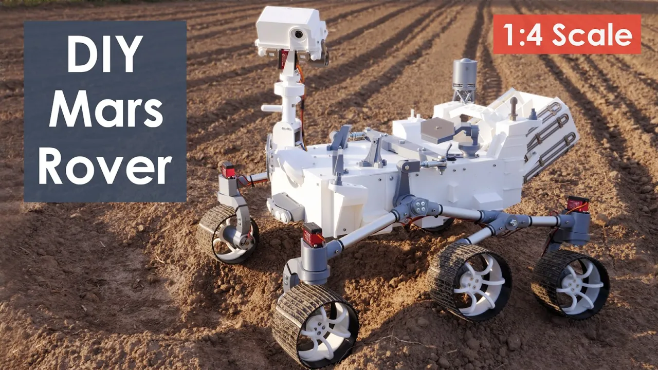
This video tutorial demonstrates how to design a space rover with a rocker-bogie mechanism using Autodesk Fusion 360, covering the complete workflow from creating the main body through sketching, extrusion, and assembly of mechanical components including the rocker, bogie, wheels, and joints, followed by adding features like cameras and solar panels, and finally applying materials and finishes to complete the design.
Rocker-Bogie Mechanism Design Tutorial in Fusion 360 for Space Rovers
Added:Basic proficiency in Autodesk Fusion 360, including 2D sketching, 3D extrusions, and parametric modeling constraints.
Fundamental understanding of CAD assemblies, specifically how to define rigid and revolute joints to constrain component movement.
Theoretical knowledge of the rocker-bogie suspension system, including its history with Mars exploration and its mechanical advantages over traditional spring suspensions.
Elementary physics concepts of kinematics, center of mass, and torque as they apply to mobile robotic platforms.
Finite Element Analysis (FEA) in Fusion 360 to evaluate the structural integrity and stress distribution on the rocker-bogie arms under planetary gravity scenarios.
Dynamic motion simulation and kinematic analysis to test how the rover behaves when traversing complex obstacles and uneven terrain.
Integration of drive and steering actuators, exploring Ackerman steering geometry and electronic control systems using microcontrollers like Arduino or ROS (Robot Operating System).
Rapid prototyping techniques, such as 3D printing and hardware sourcing, to translate the virtual CAD design into a functional physical scale model.
8.4K views103likes54:47Original Release: 2018-04-21
welcome to yet another video I actually hadn't made a video previously for a space troll simple one which had I told it quick Amazon but it had only four wheel but the project actually process to have a rocker-bogie mechanic so for the project so what I'm going to do is I have created a project workspace short on three since I already have enough files over here I've created under folder so I'm going to save my thoughts over here you know let's start at the project so as you know there are three planes except X Y and Y Z right I'm going to start with sketch rectangle such a drunkard the reason why I choose Center rectangle is that if I had chosen to point of tango I have to choose the starting one side of the rectangle and the other side of the rectangle whereas for the center point rectangle I can just choose the plane right I'm going to choose the exit plane so take that plane on I've chosen it so what I do is I click on the center this is my center point or chin all the axis X is zero Y zero ends it is so I click over there and then after that I just tried the most wherever I want so I can actually type in my x and so I'm going to take in hundred and ten the dimension I need a 3d printer is 140 millimeters red maximum capacity to print that's the reason I'm making a small prototype affair so 110 millimeter is 11 centimeter eighty millimeters eight centimeter for the project we actually require to make it bigger in size because you have to print a model so it's a we will discuss the size later on for now I'm just making a prototype of it just a small representation that's why I am going with these dimensions after I have typed my required dimensions my present when our rectangle is ready so I need to extort it now in order to extradite got to create extrude so extruder let me just try it up or type in whatever you know it's thirty members I just need around what millimeter I'm gonna even then the operation since it's the first body that's just called new body then I click OK Nassau main body now we can add the mechanisms that we need alright so this is what we are actually going to make we need mechanism for basically on one side we'd have three wheels on the other side we'll have another treatments so you need to have just rocker and then no here pokey right so let's start making outside and then later we'll be right turns out the other anyhow now what we need to do is you need to make them because I'm so I'm going to just face off my body then I go to sketch circle Center diameter circle the reason why I'm choosing it before we have this particular rock for me to have a circle or a cylinder that is connecting the booty and the rocker I need that cylinder here type in armed that message and repair on a few millimeters maybe anyway somebody's gone above it 600 in 806 again now what I need is I need two extra death so I've got to create I chose a sample first and then I will create the next row you can either click key for extra instead of going to create index or just type in E and then to Circle I mean not that just press the e button on a keyboard and then so choose a circle the extra option will be chosen automatically so I'm going to extrude it for around five millimeter let the operation be on joined because this is joined to the body right then you click OK sock what the thing down here now what I'm gonna do is I need to have I need to have a rocker built into it so before I start I need to choose this face because I'm gonna draw if you're looking from sideways I need to draw her okay sketch over on this line like five millimeter from the body so the best way to do is either offsetting the plane or choose this particular face then create a sketch line or press tab so once that is done we can go for what we need so I'm going to start my point here you have a shape almost like this so I'm gonna go for around 20 maybe this is going to be a bit too much number of 15 millimeters then I click I'm gonna undo it line stop from this point 15 years then click OK then we need to have what I'm gonna do is I'm gonna take around my degree is gonna be entering length that should be at 50 I'm not sure if it's 55 so is it so if you're not sure you know it next is go to this line that front of point where it ended type it 50 and no that's okay it's starting from here so in that case what we can do is 90 that's the case you can do around 70 maybe not 170 a 57-millimeter around 70 I have 1250 and 370 from that particular line go back to line choose from here the diameter is 6 millimeter so we need to have at least 8 millimeter just in case so I'm going to type in theta as my will be 180 degree and then I click there but it a present I think so let's just keep at this point type in 180 degree 8 and again so that I mean it millimeter for you then let's just start from scratch again what we are going to do now I need to reach this point but with a degree of hundred and ten degrees right it's 170 from this side and if you are going from this side its hundred and turn so you need to reach a point of this one so let's just say fortune but it's gonna be a bit so for John 1:5 yeah for 10.5 should be fun so 1 over 3 and 1 5 then I click on line again continue around so I'm gonna make it 55 yes yeah millimeter neck okay and then same what I need to do now is I have here I know I need to have a part and then you want line from here so before I do anything you need for this angle right so I understand 123 so should older than this one right so what I'm gonna do is I'm gonna take it up to here maximum yeah that's around 120 7.5 yeah that's just so I go at 27 how much did we take here it was 8 so we take another 8 from here to the side 8 and then pretend now we need to respond respond right so what we can do now is sketch let's start from this point I think so take since 100 and make this one a TV need 70 so the angle should be around 70 degrees and then click at 27 the next unit up to yeah 8.5 then directly link it over here all right so you have got the mechanism almost done just keep and then press the home button because then now what we need to do is we need to extrude is a bit so what I want to do I'm going to click this one and then let's not do that way let's just go to create extra then we need to choose the preferred right so if I choose just this particular is not chosen so I click at that as well so the two profiles are selected then I'm going to go for two directions okay it's rough direction one said I'm gonna go to side make sure this is new component in the body new component once that's done what you can do is go to the front view since this is a joint try to bring it a bit at least a one millimeter to the left so that it's more like it's linked to this particular part and then you can crank like two millimeter maybe and then bring this about one millimeters or total of three millimeter thickness okay if you want to show this circle what you can do is ignore that for a while I mean don't choose the circle if you need to circle outside the maraca so I just select a rocker pot no it's a circle so it will be one profile and then you keep it at a total of one on the left one on the I mean one on the back one on the front total two millimeters and then you click okay so your rocker there's now two millimeters if you need to extrude this you need to trust pull that right so you just press pull that and bring it outside it's already five millimeters if you need to show it outside what you can do is okay that cannot be done so what we can do no maybe try it out now I can go for join with our own here so let's just go with join in and check okay we need to add mechanism right so what we can do now is good assemblé has been tuned we need to try and see if the soccer would rotate around this particular joint so I choose the component which is a component these are component right that's a rocker and then it's gonna rotate around us change the type to trouble yet so we need to choose that on which position it's gonna rotate right so position choose just yeah it will rotate around that particular line then click ok we don't need to rotate 180 to 360 degree we will change the limits later so that's done now what we need to do is we need to add this joint and just rock out given this ball key part but what we can do now as you just click on this go back on this rocker part we need to create another circle and then exit it as a joint to make that connection between Raqqa and the boki so I go to here it choose the center right to choose no Center is gonna be a bit if it's what I think okay I'm gonna go with this one so the diameter mother probably six then I click enter so I was on the circle of diameter six now and I don't need this length is slain is separating the circle integer so I'm just gonna delete that I click that line under deleted right relative actually yeah that line is no no I don't need it anymore so what I'm gonna do right view you will create extra night like this particular circle and then I put back to the front view or that's just one saying what we can do I see intercept is corrected here I sure we have surplus done okay now what we can do is choose that circle go to model a create extra mile injection it for that could be around one millimeter here and choose or pressure direction to the two sides meet insight and operation should be join we are joining this thing this connection to the rock then you click OK so this joint is actually this I think we should make the outer part actually more because we're connecting the bulky so sorry about that codex road again go home choose just face we need to make it a bit more paper inside so what you can do is extruded for about yeah and make sure the operation enjoy we need a total of it's one millimeter inside and one millimeter here and now again three sort of total of five millimeters the joint should be okay that's connected now we need to matter pokey pot in order to add the bogey we need to choose this face of the cylinder go to line let's start with from this point can be fun it should be around this line where it's straight from my side sorry about that so we go here than ten degrees and then it changed okay that means it meets this but see if you can see the blue water lining me just know me it's the same as that one so yeah you click all that so we got fifty point four on four and then how much did we take here I think we took eight so I'm going to take the same now the gray put peas funky that's done now I what I need to do is keep on the straight line go for eight millimeter in 30 and then I should have line goes from here eight millimeter so that's eight point yeah diamond should be here yeah twenty three point three nine nine yeah go there then so I've got that one and it extended to this is a side and I click enter I don't need it for that I've got eight here under Anton I need to do the same thing on this as I go back to line start from this particular point how much was this one ten so I go here ten but this last and now chose this line I need this same time but in grant and again and click on ok then go back line again start from this point equally Mutoh fine so we if you are drawing a line and you flip the counter you will see the dimension if you don't see if you don't take the end I just keep continuing the lines you won't see the total dimensions for each bar okay so click on this line main iteration just particular line right so trace that and the angle should be 70 I clicked and then I click join to the spot to go there so I've got my pokey part um just need to add cylinder underneath the next row rate as well we don't need this pink line now what we need to do extra this right in order to extra it shows only the bogie not to cylinder then I go to create X road then towards the back so total of two millimeters should be none and then not join they're going form of Krishna's new component because we need to rotate does around that cylinder so it click new component and okay but now we we need to show this cylinder out so people to create extrude extrude at four to one millimeter yeah this could be joined because we are joining with the previous cylinder so trick okay so that's done now what we need to do is we need to add the cylinders for the wheels so I said we could choose the Bakke face or the rocker face so go to sketch circle Center diameter circle right face let's just keep in the home and choose which face we need I'm gonna call it Rocco I'm sorry baki face then I need to choose the center I chose as my scent and my time it also yield connection would be around four millimeter Suffolk okay I've got my circle drawn there so from the same line I'm gonna start from here climate Darfur press enter enter about my support on there as well of create circumcenter points of both from the same line for millimeter so I got that run for three circles done now what I need to do is I need to extrude this one and I actually I need to extrude all of their sofas less this if you look from this that's just see these circles are all on the on the face of BOE key whereas just face is actually a bit of gap so we need to explode it towards this one and make it as a so on okay so before we do anything that's just extra crisper distal circles on top Auggie is over to create extra which is just one on this one front let's just to circle that we selected be joined okay operation that will be joined on to this poking and I'm going to extrude it for about three organ xsf for not make sure that operation is enjoined and then it click okay so that's done now we need to see the sketches missing so we go to the sketch that a sketches this one sketch on six so I click on the show sketch and then you go to create again extra click on this and then what we need to do now is we need to export it towards back I think that's around five million okay that's for you okay cool so that's four as well so we pick story--it to us background for and then make sure the operation is then join trick okay so what we did right now this we then use the new cylinders we created we actually joined it to the rocker as well as the bogies so we can hide the sketches now - special anymore now what we need to do has been to create our wheels to create the viens go back to sketch circle Center diameter circle and you can choose a face hostess particular alright so I've got this down and then I'm gonna sketch on the center of it yeah that that was my Center and let's keep the real diameter be around 20 million okay so I'm gonna keep it on for maybe 15 15 should feel fine oh I'm gonna bother 20 and then I click enter I've got a sketch for the deal done what I'm gonna do is I'm just gonna sort one beam create the wheel and then just copy to the other cylinders but the problem now is if you look from the side see this is only four millimeter says four millimeter further forms so we need to make sure all of them are on line so we can what we can do now is we can extrude space for extra four millimeter to the side right so when you look from the back all of them are on the same line then you click okay now that we have the sketch you select that you make sure to select the center part as well so let's go to create so this okay so we chose this one first what you can do now is make sure that it is actually joined to the cylinder or maybe let's just cancel this millimeter okay let's just make it zero go back to window make sure select a circle inside but the problem is that if he chooses oh yeah let's just do the circle inside and then make sure this is a new component okay no joint component and once that is done you can exert it as much as you turn it around for medium a five-millimeter como beans so I'm going to click OK now so I've got my cooking done but I am gonna for a particular design for my BD for that if you look here now we are so in the body section we have only one body alright so just keep that in mind we have only one body as of now so go to the right view what I'm going to do now okay let's just not go to over yet I am gonna make design for my view so I put a sketch line and then I choose this face of the meal as my profile de Bob which is it's up to you what dimension yet I just drag down which was three millimeter in this length and one millimeter wide and then I press escape and it is pink line I'm going to delete that okay so I'm gonna go to create extra choose this new body and I'm extra now I've got this body created on top of my views anyhow I need to do these small bodies into a circular pattern so I bought to create pattern so club battle okay some kind I've been moved okay let's just return to our thing yeah that's perfect we got create create pattern pattern just a pattern tape should be changed to bodies my choose to join the body so let me just say again and then let's be new 40 new body mixer for one millimeter operation new body click ok then go to create extra money to create extra yet so we need to have his body into a pattern for create pattern circular pattern then choose pattern tapers bodies then it choose this body and then column which axis I needs it along this particular axis and how many do I need I need around 15 all right click ok so now I have 15 new borders before I only one body now have total of 16 15 plus 1 is 16 so what I'm going to do is I'm going to choose this face of each bodies so let's go to create extra fun so 3 4 5 6 7 8 9 10 11 12 13 14 15 and then I'm gonna extradite towards back chosen now a total of 50 extra towards the back so all of them gets cut okay let the operation one cut and then put click ok now as you can see the shape of the real teeth there's actually I'm a tank truck so I not tied to of 10 track pattern for the wheel and it see that or for the space rover to climb uneven land right so I've got the key being done I don't need these last 15 bodies anymore because I if you cut it out so I'm gonna need all of them surely all right now I have one body which is now if you can see this component three years our wheel so I'm gonna copy this component okay right click on it then go to the coffee and then create a copy you can make it as a body if you want but then that's not a body right so this is cover to continent because we actually chose component right so right click move coffee click on create copy go to the right view make sure to place it on the center of it so if you can see that's okay so again click copy that's done the mechanics are actually physically done but we need to show so if I go to the joint so far I have made this one that's not writing around okay and the problem is that you need to put limits to it so I quote I'm not in right click on it that it's on limits then I click on minimum gets chosen so the minimum or the maximum I'm going to put minimum at minus 30 maximum master key right Matic okay so if I go for the animate model now it will only move up to a degree of 30 okay then change the name if you want to click on it oh you can go and add a square join for sabaki so you click on this builds on click on the bogey and then the rocker because it's in cylinders attached to that rocker then choose this pattern yeah then you click okay so now we can double click and rename this s4k you ready see Edmodo it just goes on yeah no enjoin limits minimum maximum - 45 and ok now we need to add mechanism for the wheel so what we can do is assemble a spell on - Sabine then choose Tsubaki wrong which axis ok and then join keep repeating as long as you need don't just say click okay now I've got all the wheels done no I see see that's done animate mode oh yeah then we have read all the mechanisms are done now we need to add more features to this anything I need mirror into the other side so I'm gonna do now if I don't have this joint but it's a piece of body on my other side so I might have to sketch the same see if I chose for mirroring create yah easy I can then let's bodies this is as a whole body so if i murder it i will have two bodies as I have neither so what I'm gonna do now is need to measure to measure the diameter of the first part of it one we'd actually let's go to inspection myself okay so a meter diameter is 6 millimeter so I need to create the same mmm so for that what I'm gonna do now is basically simple I show my origin I go to construct offset plane which is this plane I need to offset it that's for hitting the circle at the same point so I offset it before and I keep it on the slide and then I click OK when I go back I choose this plane and then I go to sketch circle send the diameter circle I come here this was my Center six millimeter wide so I click OK so if I go back to the other side I will have a circle here see all right I've got that done and almost exploded earlier for sure right to show the height now I think I did it for around five millimeters most probably how much did I do here let's see five Dismas five one two three four five six seven that was a total of seven nine eight seven okay now I can mirror the whole thing if I need to so I got to mirror I choose chosen everything clear a plane [Music] what Naraku buggy on both sides now whatever is left is basically to add features to it so if you need a camera go to circle send a diameter circle shows here you can have a camera on the bottom front or the back whichever you consider just the front or back so yeah around I'm gonna I'm gonna I'm gonna keep the camera as a new component then I click okay right so I've got the new component done to have the shape of camera I go to modify fillet maybe this then I hide yes let's say I don't know what is the matter I think I'm gonna go with three so that's the shape of my camera I think of the same they chose my go through the back face altered around and then I go for yeah let's go for back face sketch circle center diameter circle just this face yeah 13 millimeter from that bottom is my center of the camera so I got the line choose this way average joe's that race and I got to 30 millimeter but he actually must be 15 actually let's just go for line click on the same to go for 15 that's 5 10 15 years so that should be the Circle Line so eat like juice I mean diameter done like vacuum wisdom if I need had more features I can do that as well what I can do now is I can add this all up and on the top and maybe a camera or sometimes those features so in order to do that I'm gonna draw a line go for this face on the top so I'm gonna make the pokey part in the pokey part as my friend I'm the rock apart as my back so before I draw the solar panel is just add a camera onto the top right table of works gets circle the time to circle ok the face is already chosen and then I come here choose this yes 10 millimeter that should be fine then I extrude it to the top yeah millimeter and just be yeah join to this one because I can rotate the camera the way sound so let us be joined and I click okay so I've got that done now what I need to do is then you just show my origin I need to add a camera right so what my plan is to add a camera or what you get I mean horizontally to this particular cylinder so I choose this plane and then I go back to circle I'm sketch circle which is centered on yourself oh yeah then come to this point okay yeah it's around two after I'd say but it's slightly the sketch for my camera then what I do is create extrude it was this sketch of the circle then I choose this directional symmetric I need because I don't goes and now I'm gonna extrude it so you can see that it's getting its lower equal amount that's around 25 millimeter add this as a new component then I click OK so that camera top is my new component I need to add the curve to both sides so I go to modify fillet I choose this and try to yeah what should be fine okay so that's done now I need to add solar panels on to the top so for that I can go to sketch line and then I click on the top of the face top face also oh sorry so let me start from this point to teach 30-27 to name is outside to space over to get maximum capacity I go to create extra this to choose outside so I've chosen both this I can make it as a new component if I want to but let's just go with new body because I'm not gonna rotate it or anything it says solar panel on top of it so I click Next or as much as I need let's just go with Chen okay so minutes out there is also ignore it [Music] [Music] [Music] one two three four five six I need survived sort of to eight inches and then this is good bye yeah why should be fun if you want to build this let's just go for three or four or five each other you feel okay if I'm gonna go with five Knightly cookie no I need to shout for a bit so I go to modify chamfer selector stage three yeah it looks like so that's done so it's almost done now all we need to do is add colors or if you want to add a camera on the bottom you can do that if you want to add anything more any features like for sample collection you need to drill you can add a third and XO death and then make it as a rotating part and then say it's a sample collective mood trailer or something now I'm going to go to more so in this part you can actually add colors or whatever you need all right so let's go quickly to finish it off in order to add colors or materials go to the appearance okay this is the one then the star box a lot you can either choose the bodies or maybe the faces if you need which face you wanna add and stuff right so let's just go for meals first I'm gonna go for the mean suicide what where is it above a can offend drop well yeah we hear that means I'm gonna a dropper heart although is actually caught up a hot you know you can add colors for the faces of the body or whatever you need so for now I'm just going to poke the paint the material recommend it as Steve or anything of that sort so for paint I'm going to go get glossy do they have the faces of this one yeah so I'm going to add to this so I will add this to all the corners [Music] [Music] yeah nothing the camera should be I can choose method steam steam steam steam then [Music] if you want to change the philosophy you can still change it in the page glossy materials for the front and the back since it's for MS machine if you want to add logo you still can do it so you can click close on - go to tikka alright select the image if you have already downloaded you can search in Google in getting these foamy which I already have I need to choose the face image insert round to this one so that's done if you want to you can do that as well so another one so I choose I choose this face you cannot just it yeah turn back it's up to you I want to keep it so you could make it okay and see I can do the same if you want don't forget to add the joint aspirin to this week's I only added over here I thought for you you have to do it just as well got my face forward you can run right capture image if you want run window sighs okay this is what you want to save it you can save to my computer it shows where you want to save it for me yeah image space so I click okay so having it binomial you made space over and image done good luck
Up Next
14:02
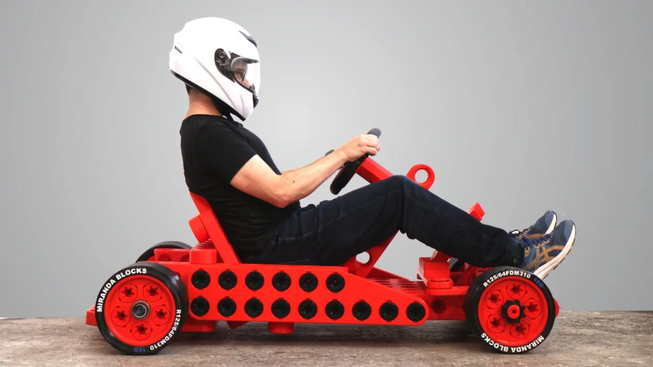
3D Printed Go-Kart Chassis: Design and Assembly Process
@ivanmirandawastaken
275K views•2023-03-21

12:54
Triumph of Orthodoxy Icon: Byzantine Art & History Explained
@BenCallan
2.1K views•2024-08-06

9:49
FastAPI vs Flask vs Django: Choosing the Right Python Web Framework
@TechWithTim
302.5K views•2024-05-26

1:42
Game of Thrones Opening Credits: A Cinematic Analysis
@gameofthrones
46.3M views•2011-04-18
Related Study Plans & Knowledge Roadmaps
Structured learning paths in General & Interdisciplinary Studies
general-studies
Elevator Engineering: History, Physics & Cities
01From Hoists to Safety Brakes: The Dawn of Vertical Lift
02Hydraulic vs. Traction: The Engineering Physics of Elevators
03Modern Speed, Safety, and Algorithms
+ 2 more learning modules
12h5 modules
Explore Roadmap
general-studies
Rubber: Material Science, History & Geopolitics
01Origins of Natural Rubber & Mesoamerican History
02The Chemistry of Natural Rubber & Vulcanization
03The Geopolitics of the Rubber Boom & Colonization
+ 2 more learning modules
12h5 modules
Explore Roadmap
general-studies
Containerization: Evolution, Logistics & Trade
01Ancient Trade & Bulk Cargo: Amphorae to Barrels
02The Industrial Revolution & Cardboard Packaging
03The Containerization Revolution: Malcom McLean
+ 2 more learning modules
12h5 modules
Explore Roadmap
general-studies
Textile Tech: Evolution, Labor & Global Impact
01Pre-Industrial Textiles: Handloom & Cottage Industry
02Mechanization: The Spinning Jenny to the Power Loom
03The Factory System & Global Labor Transformation
+ 2 more learning modules
10h5 modules
Explore Roadmap