Writing an x86 OS: Kernel, Assembly & C
Learning Goal: Write a basic x86 operating system kernel from scratch using C and Assembly to understand low-level system execution. This curriculum guides you from bare-metal execution to managing hardware interrupts and drafting custom screen drivers.
- Estimated Total Study Time: 40 Hours
- Prerequisites:
- Basic familiarity with programming logic (variables, loops, and pointers in any language).
- Access to a modern operating system (Linux, macOS, or Windows via WSL) capable of running terminal utilities, an emulator (QEMU), and compiler tools.
Module 1: Computer Architecture & Assembly Foundations
Module Overview
To program directly on hardware, you must first strip away the high-level abstractions of modern runtime environments. This module establishes a strong understanding of how the Central Processing Unit (CPU) executes instruction sequences, interacts with main memory (RAM), and coordinates data processing via registers. You will learn the fundamentals of x86 assembly language from absolute scratch, setting up your mental model of the Von Neumann architecture.
Recommended Videos
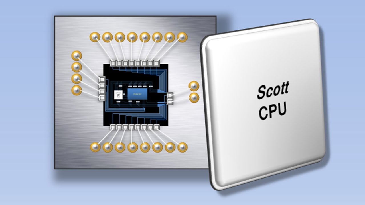
Why this video
This classic visualization provides a perfect introduction to computer systems. It details the fetch-decode-execute cycle of a CPU, showing how control units, registers, and memory buses work together. Observing the physical movement of instructions from RAM to the processor makes the low-level execution pipeline easy to understand.
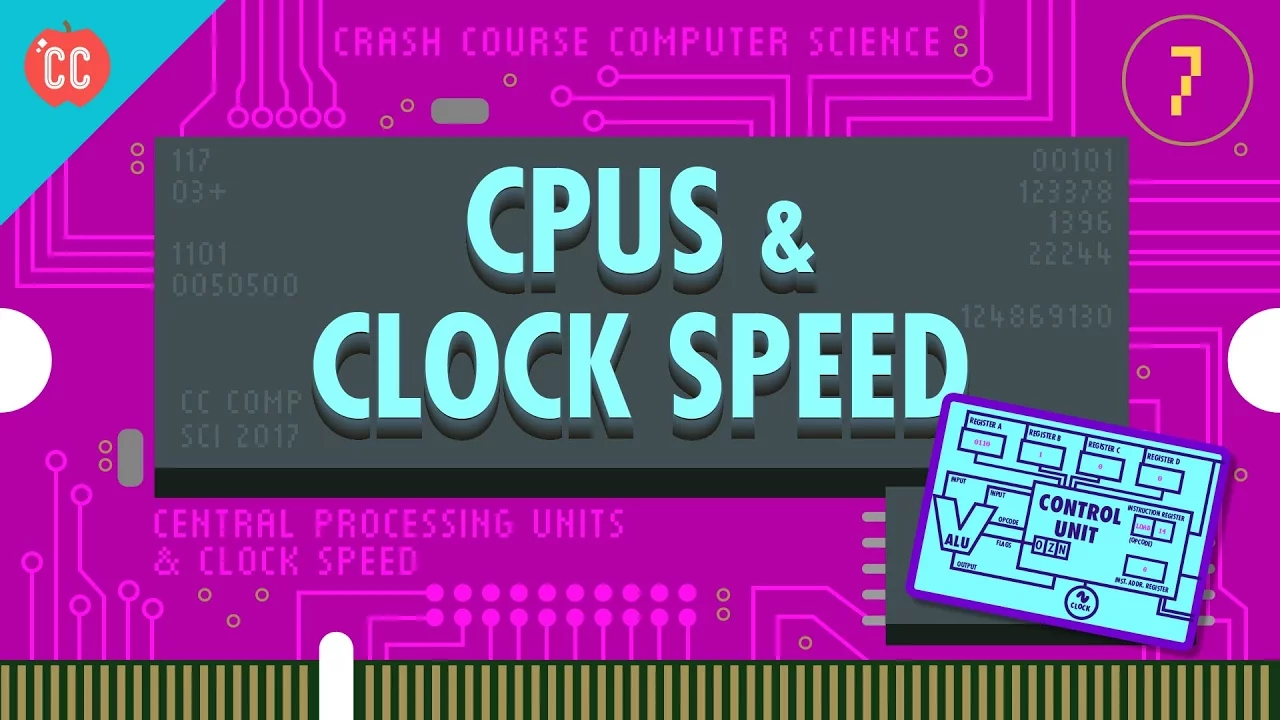
Why this video
This video explains the microarchitectural blocks of the CPU, including the Arithmetic Logic Unit (ALU) and system registers. It explains how high-level programmatic logic is compiled down to raw binary states, providing the context needed for hardware-level programming.

Why this video
This tutorial transitions you from hardware theory to actual assembly programming. It explains x86 registers (EAX, ECX, ESP), arithmetic instructions, and how parameters move on the memory stack.
Why this video
Operating systems manage data storage directly in memory. This video explains how to read and write memory locations in assembly, configure pointers, and use size directives (DB, DW, DD) to define global data in your raw binaries.
Knowledge Checkpoint
- Detail the exact components of a CPU's fetch-decode-execute cycle.
- Explain the difference between registers, RAM, and storage buses.
- Write x86 assembly instructions to move values between registers and memory.
- Use size suffixes (such as
byte,word,dword) to define and load variables of different sizes.
Module 2: The Boot Sector & Real Mode
Module Overview
When an x86 computer powers on, it starts in 16-bit Real Mode, mimicking the original Intel 8086 processor. It executes firmware known as the BIOS (Basic Input/Output System). The BIOS runs basic diagnostic checks (POST) and loads exactly 512 bytes from the first sector of the bootable media—the Master Boot Record (MBR)—into memory address 0x7C00.
In this module, you will write a functional 16-bit bootloader in x86 Assembly. This bootloader will call BIOS interrupts to write text to the display and read keyboard inputs.
Recommended Videos
Why this video
This video walks you through writing your first 16-bit bootloader. It explains the significance of the 0x7C00 loading address, how to invoke basic BIOS interrupts to render text, and why you must terminate your 512-byte sector with the magic boot signature 0xAA55.
Why this video
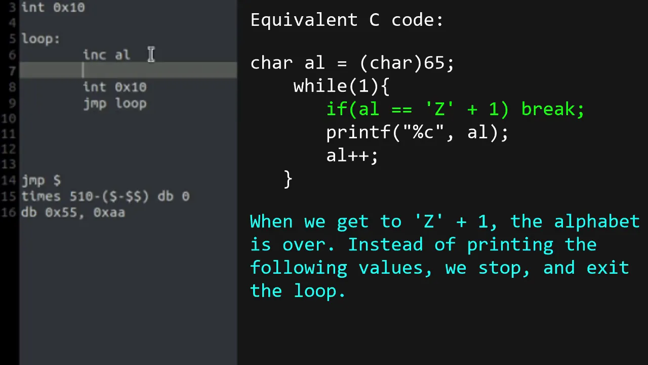
This practical guide shows how to write loop structures, handle memory offsets, and use conditional jumps in a bootloader. These techniques allow you to process data sequentially and build interactive prompts.

Why this video
This video explains the mechanics of BIOS interrupts (specifically INT 0x10, service 0x0E for teletype output). It shows you how to write custom print functions in x86 assembly to output entire strings to the display.
Knowledge Checkpoint
- Explain why the bootloader must be exactly 512 bytes long and end with the bytes
0x55and0xAA. - Explain why the bootloader program is loaded at memory location
0x7C00. - Call the BIOS interrupt
INT 0x10(service0x0E) to write characters and strings. - Write assembly code that performs conditional jumps based on comparisons (
cmpandje/jne).
Module 3: Transitioning to 32-bit Protected Mode
Module Overview
16-bit Real Mode limits memory access to a maximum of 1MB and lacks memory protection, allowing any process to read or write any address. To build a modern kernel, you must switch the CPU to 32-bit Protected Mode.
This transition requires configuring the Global Descriptor Table (GDT), which defines memory segment limits and access rights. You will also disable BIOS interrupts and set the control register cr0 to activate Protected Mode.
Real Mode (16-bit) -> Limit: 1MB RAM, No Security │ ▼ Define GDT (Segment Bases, Limits, Privileges) ▼ Disable BIOS Interrupts (cli) ▼ Set CR0 Register PE Bit (Protection Enable) ▼ Perform Far Jump (Flush Pipeline) │ Protected Mode (32-bit) -> Limit: 4GB RAM, Kernel vs User Privileges
Recommended Videos
Why this video
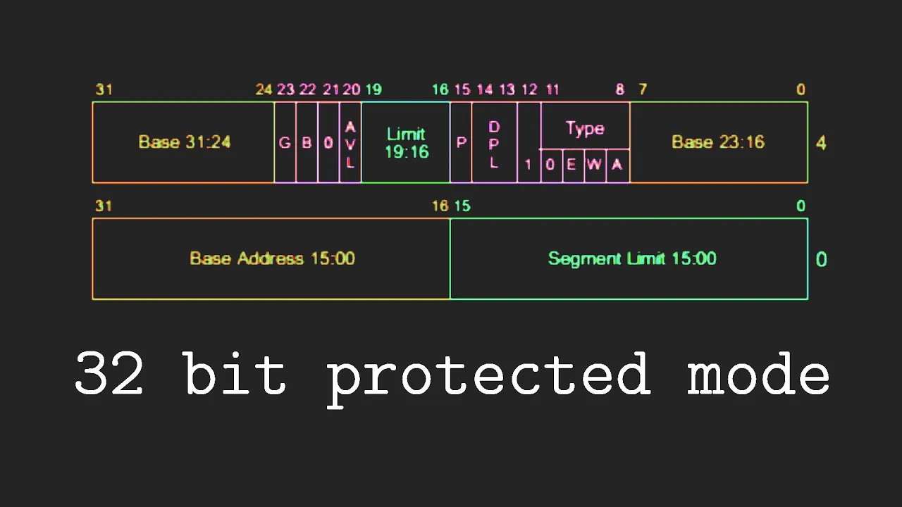
This step-by-step tutorial demonstrates how to define a 3-entry GDT (Null segment, Code segment, and Data segment), load it using the lgdt instruction, and execute the far jump needed to switch to Protected Mode.
Why this video
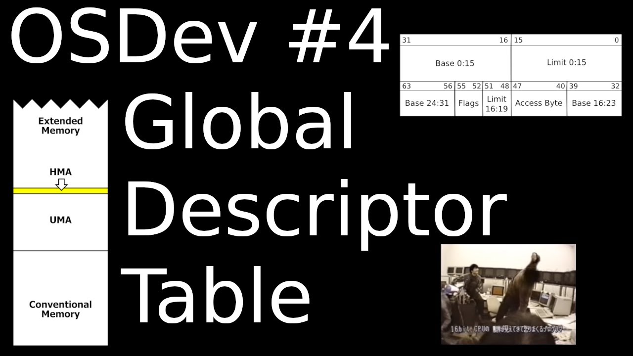
The x86 GDT structure is notoriously complex. This lecture explains its layout, including segment base addresses, limits, privilege levels (DPL), and type flags, helping you configure it correctly.
Knowledge Checkpoint
- Describe the binary layout of an 8-byte GDT segment descriptor.
- Explain why BIOS interrupts can no longer be called once you transition to Protected Mode.
- Explain why a "far jump" is required immediately after modifying the
cr0control register. - Implement a minimal, valid GDT configuration in assembly containing Null, Kernel Code, and Kernel Data descriptors.
Module 4: Setting Up the C Environment & VGA Driver
Module Overview
Operating system kernels are rarely written entirely in assembly. Instead, assembly is used for the minimal startup routine, which then transfers control to a main function written in C.
This transition requires a cross-compiler to generate target x86-ELF binaries independently of your host OS's native architecture. It also requires a linker script to organize your code and data sections in memory.
Once your C runtime environment is ready, you will write a VGA text-mode driver to print characters directly to screen memory.
Gap Acknowledgment & Guidance: Since modern YouTube libraries lack comprehensive tutorials on building an
i686-elf-gcccross-compiler from scratch, the videos below focus on build automation theory, linker scripts, and VGA memory mapping. To set up your toolchain, you should compile the source code for GCC and Binutils with--target=i686-elfon your host system, or use a prepackaged cross-compiler toolchain inside a Docker image or package manager (such asgcc-multilibori686-elf-gccvia Homebrew).
Assembly Code (boot.asm) C Code (kernel.c) ┌─────────────────────────┐ ┌────────────────────────┐ │ - Set up stack pointer │ │ - void kernel_main() │ │ - Call kernel_main ────┼────►│ - Print messages │ └─────────────────────────┘ │ - Run main loop │ └────────────────────────┘ ▲ ▲ └──────────────┬───────────────┘ │ Linker Script (link.ld) ┌──────────────────────────────┐ │ - Merge .text, .data, .bss │ │ - Align to 4KB boundaries │ │ - Output ELF file │ └──────────────────────────────┘
Recommended Videos
Why this video
This video explains how cross-compilers work. It shows why host-system libraries must be bypassed when building bare-metal programs, helping you understand why standard headers like <stdio.h> cannot be used in a kernel.
Why this video
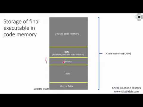
Linker scripts define how compiled code and data are organized in memory. This tutorial explains sections like .text, .data, and .bss, alignment constraints, and how to write a custom linker script to organize your binary.

Why this video
This guide shows how to bridge your bootloader, compiler toolchain, and C code. It demonstrates how to compile C files, assemble assembly components, and link them together into a final bootable operating system image.

Why this video
In Protected Mode, writing text to the screen is done by writing characters and color attributes directly to the VGA video memory buffer starting at address 0xB8000. This video shows how to build a VGA driver in C to print characters, update cursor positions, and clear the screen.
Knowledge Checkpoint
- Explain why you cannot use your host operating system's native compiler (like standard
gccorclang) to compile your kernel's C code. - Write a basic linker script that maps the boot sector entry point to its load address and groups
.textand.datasections. - Describe the layout of the VGA text-mode memory buffer starting at address
0xB8000. - Implement a C function,
print_string(char* text, char color_attribute), that writes character bytes directly into VGA memory.
Module 5: Interrupts, Inputs, and Kernel Mechanics
Module Overview
To respond to hardware events like keyboard presses or system timers, your kernel must support hardware interrupts. In x86 architectures, this requires configuring the Interrupt Descriptor Table (IDT), which maps interrupt vectors to Interrupt Service Routines (ISRs) written in assembly.
You must also reprogram the dual 8259 Programmable Interrupt Controllers (PICs). By default, the PIC maps hardware interrupts to CPU vectors that conflict with internal exception vectors. You will reprogram the PIC to remap hardware interrupts to a safe, non-conflicting offset (such as vector 0x20 onwards).
Hardware Event (e.g., Key Press) │ ▼ [ 8259 PIC (Remapped to 0x20) ] ────► Signals CPU Interrupt │ ▼ [ IDT (Interrupt Table) ] │ ▼ Interrupt Service Routine ┌─────────────────────────┐ │ 1. Push All Registers │ │ 2. Call C Handler │ │ 3. Send PIC EOI Signal │ │ 4. Pop All & iret │ └─────────────────────────┘
Recommended Videos

Why this video
This video explains the IDT structure, explaining IDT gate descriptors, task gates, and trap gates. It shows how to register an interrupt handler and explains the difference between regular function returns and the IRET (Interrupt Return) instruction.

Why this video
This video details the internal architecture and pinout configurations of the 8259 Programmable Interrupt Controller (PIC). Understanding its cascading master/slave configuration is essential for remapping interrupts.

Why this video
Once the IDT and PIC are configured, you can process input events. This tutorial shows how to send End of Interrupt (EOI) commands back to the PIC controllers, read input scan codes, and translate key releases.

Why this video
This comprehensive video integrates the concepts of this module, walking you through configuring your IDT entries, reprogramming the PIC, reading scan codes from port 0x60, and implementing a keyboard driver.
Knowledge Checkpoint
- Describe the structural format of an IDT entry, detailing segment selectors and gate execution privileges.
- Explain why the 8259 PIC must be remapped in protected mode, and write the sequence of initialization commands (ICWs) to complete this remapping.
- Implement an assembly wrapper ISR that preserves register states, calls a C handler, sends the End-of-Interrupt (EOI) byte
0x20to the PIC, and exits viairet. - Write a keyboard driver in C that reads scan codes from I/O port
0x60and prints characters to the screen.
Course Map
Key People Index
- Linus Torvalds The creator of the Linux kernel. His early work on writing a terminal emulator that booted on his Intel 386 machine is a classic example of modern, custom OS development.
- Daedalus Community An educational content creator who produces highly detailed tutorials on 32-bit x86 OS development, providing clear guidance on the transition from Assembly bootloaders to C kernels.
- Kelsey Steele & Nischala Yelchuri Linux kernel contributors and educators who advocate for understanding bare-metal development, helping students bridge the gap between educational hobbyist kernels and modern, enterprise-scale operating systems.
Final Self-Assessment
To verify your kernel's functionality, ensure you can check off every item in this list:
- Write a 16-bit bootloader that boots on bare metal (or an emulator like QEMU) and prints a welcome message.
- Define a valid Global Descriptor Table (GDT) and successfully switch the CPU to 32-bit Protected Mode.
- Configure a target cross-compiler (such as
i686-elf-gcc) and write a linker script to build an un-poisoned, flat binary executable. - Initialize a stack pointer in assembly, call your C main entry point, and write code that compiles assembly files and C modules into a unified kernel image.
- Implement a custom VGA text-mode driver in C that outputs text to memory address
0xB8000and handles newlines, scrolling, and basic formatting. - Build and register an Interrupt Descriptor Table (IDT) containing standard ISR exception handlers.
- Reprogram the dual 8259 PICs, mapping hardware interrupts away from exception vector addresses to a safe range (vectors
0x20to0x28). - Implement a keyboard driver that handles keystroke interrupts, reads keyboard scan codes from I/O port
0x60, and prints characters to the screen.