Building Snake Robots: ESP32, Gaits & Servos
Learning Goal: Design and assemble a multi-segment biomimetic snake robot, programming lateral undulation and sidewinding locomotion gaits using chained micro-servos and an ESP32.
Estimated Total Study Time: 26 Hours
Module 1: Foundations of Snake Locomotion & Kinematics
In this module, you will explore the biology and physics of serpentine movement. You will learn how natural snakes leverage friction and muscle waves to move across surfaces, and examine the foundational mathematical models—specifically Shigeo Hirose's Serpenoid Curve—used to translate biological slithering into joint-by-joint robotic control.
Recommended Videos

Why this video is valuable: This highly engaging video breaks down the biological locomotion methods of snakes, demonstrating the mechanics of rectilinear, serpentine (lateral undulation), concertina, and sidewinding gaits. It explains how belly scales provide anisotropic friction (low resistance sliding forward, high resistance sliding sideways), which is the physical principle that allows lateral undulation to generate forward thrust.
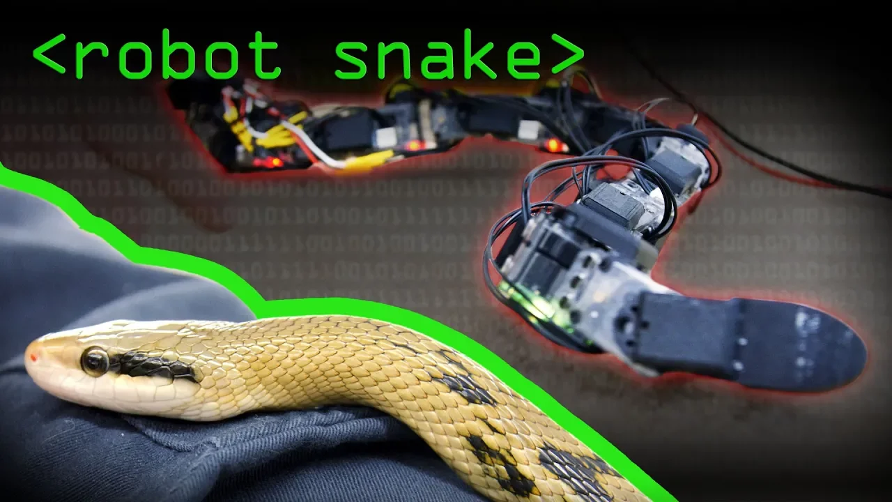
Why this video is valuable: This video transitions biological concepts into engineering realities. It explores how snake robots utilize a series of linked segments to replicate complex patterns. It discusses how 3D gaits such as sidewinding are formed by combining two separate sine waves, and outlines the physical advantages snake-like robots have in search-and-rescue and pipe-climbing operations.

Why this video is valuable: To program a multi-segment snake, you must understand kinematics—the mathematics of motion. This Stanford lecture provides a academic foundation in robotic kinematics, explaining coordinate frames, degrees of freedom (DoF), and joint linkages. This is critical for modeling how a sequence of hinge joints behaves as a collective snake body.
Core Kinematic Concept: The Serpenoid Curve
While high-level kinematics lectures cover general arm coordinates, snake robots rely on a specific spatial formula first characterized by Dr. Shigeo Hirose. The Serpenoid Curve represents the target winding angle of the -th joint as a function of time :
Where:
- is the amplitude of the wave (controlling the winding tightness).
- is the temporal frequency (controlling the propagation speed).
- is the spatial phase shift (controlling the wave frequency along the body length).
- is the joint index (0, 1, 2... ).
- is the angular offset (used to steer the robot left or right).
Note on Pool Gaps: The core video pool lacks a direct derivation of this formula. Ensure you review the mathematical breakdown above, as it is the framework you will code in Module 4.
Module 1 Knowledge Checkpoint
- Explain how anisotropic scale friction enables a snake to generate forward thrust from lateral movements.
- Define the four primary biological gaits of snakes: lateral undulation, sidewinding, concertina, and rectilinear.
- Identify how many degrees of freedom (DoF) are present in a 1D snake robot with 8 hinge joints.
- Explain how the variable in the Serpenoid Curve formula changes the path of a snake robot.
Module 2: ESP32 Microcontroller & Multi-Servo Control
In this module, you will shift from theory to control systems. You will learn to configure your ESP32 environment, interface with the PCA9685 16-channel PWM controller over I2C, and safely manage high-current wiring diagrams to prevent power spikes from resetting your microcontroller.
Recommended Videos

Why this video is valuable: This tutorial walks you through setting up an ESP32 development board from scratch. It explains how to install USB-to-UART drivers, configure the Arduino IDE Board Manager, and upload your first test scripts. You will understand how the ESP32’s superior speed (240MHz dual-core) allows it to run complex trigonometric kinematic calculations much faster than an standard 8-bit Arduino.
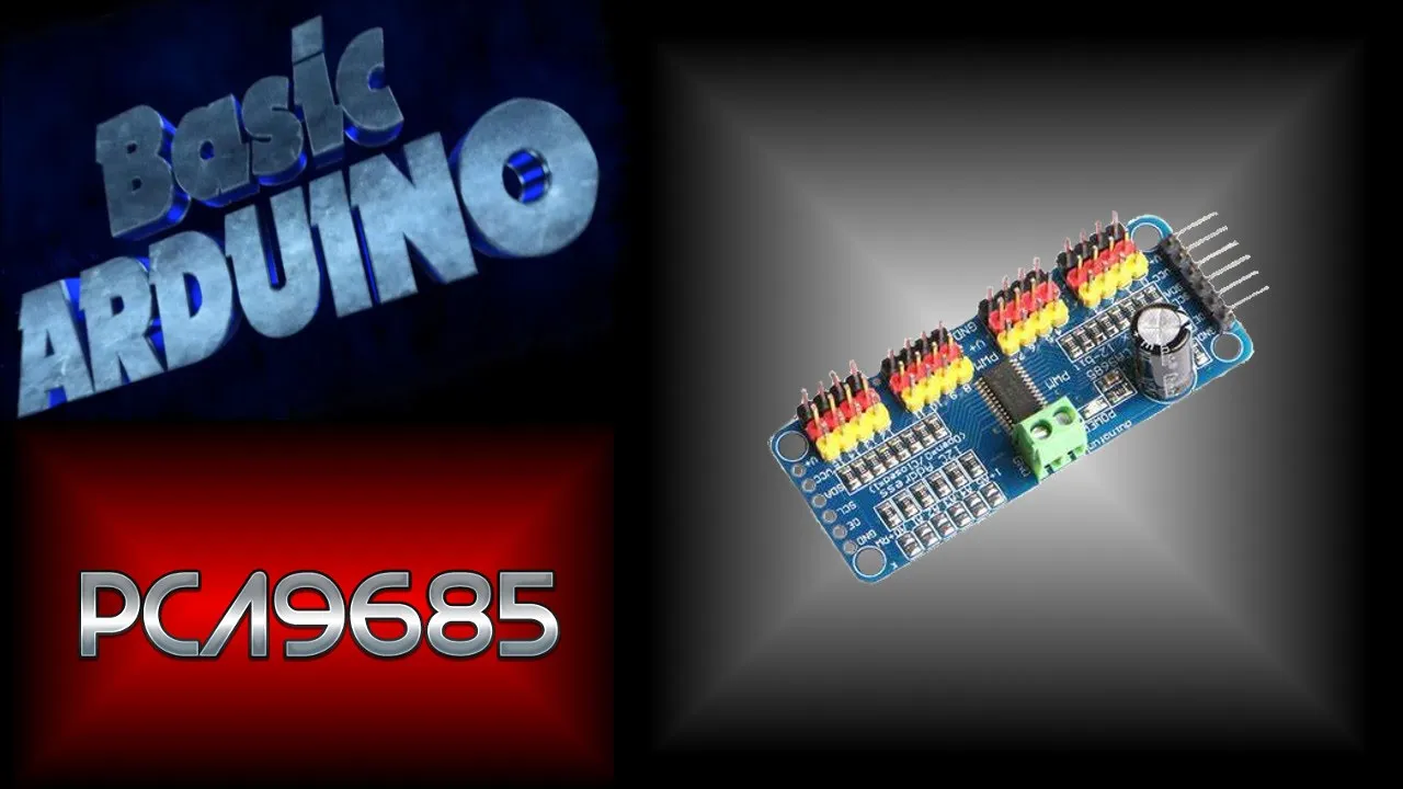
Why this video is valuable: A snake robot requires many joint servos (typically 8 to 16). The ESP32 cannot drive this many PWM pins directly without consuming all processing overhead. This video explains how the PCA9685 uses the I2C protocol (requiring only SDA and SCL pins) to offload the 12-bit PWM generation, keeping the ESP32’s CPU free for gait calculations.

Why this video is valuable: Power distribution is one of the most common failure points in mobile robotics. This video demonstrates how to safely isolate your logic power (ESP32) from your actuator power (servos) using the PCA9685’s terminal blocks. It teaches you how to estimate current draw (12–16 micro-servos under load can easily draw over 5–10 Amps) and prevent system resets.
Module 2 Knowledge Checkpoint
- Successfully configure the Arduino IDE to compile and upload code to your ESP32 board.
- Connect the PCA9685 to the ESP32’s hardware I2C pins (typically GPIO 21 for SDA and GPIO 22 for SCL).
- Explain why you should never power multiple servos directly from the ESP32's onboard 3.3V or 5V voltage regulators.
- Wire an external high-current power supply to the PCA9685 terminal block while maintaining a common ground with the ESP32.
Module 3: Mechanical Assembly & Power Systems
In this module, you will design and construct the physical body of the snake robot. You will learn to construct modular, alternating 3D-printed joint segments, analyze joint rotation limits to prevent mechanical collision, and configure battery systems using buck converters to supply high current.
Recommended Videos
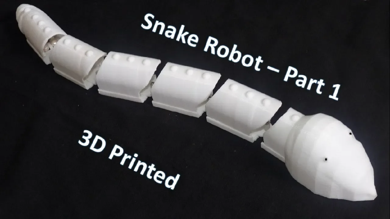
Why this video is valuable: This practical construction video details the mechanical assembly of a modular 3D-printed snake robot. It shows how servos are seated within structural frames and linked to neighboring segments. Pay close attention to how alternating joint orientations (horizontal vs. vertical) are utilized to facilitate 3D gaits like sidewinding.

Why this video is valuable: Your robot will likely run on a high-voltage Lithium Polymer (LiPo) battery (such as a 7.4V 2S or 11.1V 3S pack). Because typical micro-servos (like the SG90 or MG90S) operate at 5V–6V, you must use a DC-DC buck converter to step down the voltage. This video explains how buck converters work with high efficiency, which prevents energy from being lost as excess heat.
Why this video is valuable: This demonstration provides a clear mechanical reference for multi-servo robotic platforms powered by LiPo batteries. It illustrates the assembly layout, showing how high-current step-down buck converters sit between the battery pack and the multi-servo control shield.
Mechanical Assembly Principles
When assembling your snake robot's links:
- Mechanical Clearance: Ensure each segment can rotate at least without physical interference from wiring or neighboring shells.
- Servo Zeroing: Before mounting your horn linkages, connect your servos to the PCA9685 and programmatically write a (neutral) position. Mount the horns so that the joint is perfectly straight when at .
- Alternating vs. Single-Axis: If you plan to only perform lateral undulation, align all servos vertically so that all joints swing horizontally. If you plan to sidewind or climb, alternate each segment relative to the last (Segment 0 horizontal, Segment 1 vertical, Segment 2 horizontal, etc.).
Module 3 Knowledge Checkpoint
- Assemble at least 8 mechanical segments of the snake robot with securely mounted servos.
- Programmatically center all servos to their neutral 90-degree position before securing the output horns.
- Connect a 2S or 3S LiPo battery through a high-current buck converter, adjusting the potentiometer to output a steady 5V–6V DC.
- Inspect the wire harness routing to ensure no cables are pinched or stretched when the joints flex to their mechanical limits.
Module 4: Programming Lateral Undulation Gaits
In this module, you will develop the core software that drives the snake forward. You will write code that calculates the Serpenoid Curve dynamically and propagates this mathematical wave through your chained servo motors.
Recommended Videos
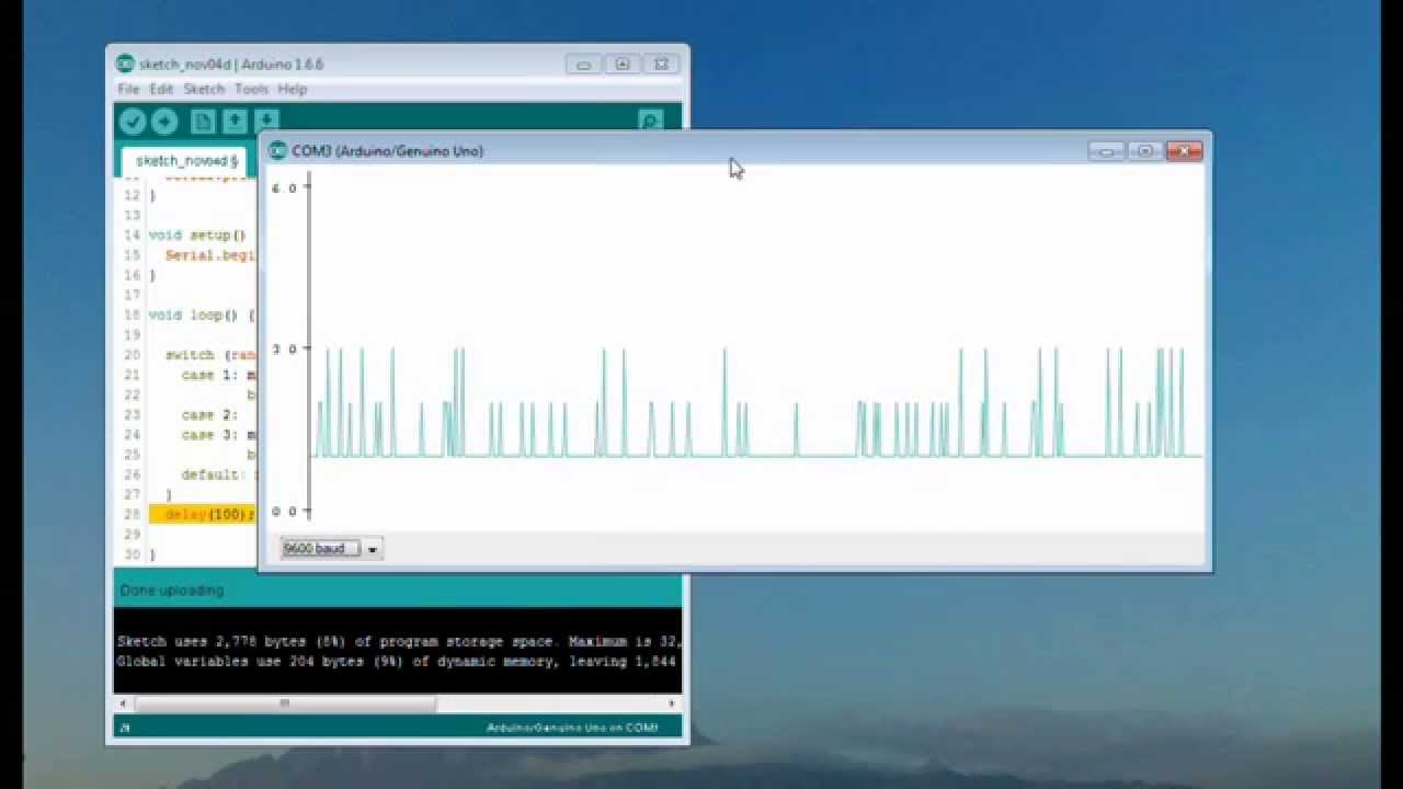
Why this video is valuable: Before loading code onto a physical snake robot, it is helpful to visualize your mathematical waves. This video demonstrates how to use the Arduino Serial Plotter. By printing your target joint calculations via the Serial interface, you can verify that your phase offsets are forming smooth sine waves rather than erratic curves.

Why this video is valuable: This design video details the physical testing and debugging of modular multi-joint vehicles. It walks you through matching physical linkage movement to code, debugging unexpected phase shifts, and tuning lateral articulation profiles to keep mechanisms from fighting themselves.
Step-by-Step Programming Guide & C++ Template
Note on Pool Gaps: Because the video library lacks a direct step-by-step code tutorial for programming lateral undulation on an ESP32, utilize the following code block as your starting point.
Assuming you are using a 1D snake (all joints swing horizontally, connected to PCA9685 channels 0 to ):
#include <Wire.h> #include <Adafruit_PWMServoDriver.h>
// Initialize the PCA9685 driver (Default address: 0x40) Adafruit_PWMServoDriver pwm = Adafruit_PWMServoDriver();
#define USMIN 600 // Minimum pulse length out of 4096 (approx 0 degrees) #define USMAX 2400 // Maximum pulse length out of 4096 (approx 180 degrees) #define NUM_SERVOS 8 // Number of segments
// Serpenoid Parameters float amplitude = 35.0; // Wave amplitude in degrees float spatial_phase = 0.6; // Phase shift between adjacent joints (beta) float speed_coef = 4.0; // Speed multiplier for the temporal wave (omega) float steering_offset = 0.0; // Left/Right trim (gamma)
void setup() { Serial.begin(115200); pwm.begin(); pwm.setOscillatorFrequency(27000000); pwm.setPWMFreq(50); // Standard Analog Servos run at 50Hz delay(10); }
// Helper to map angles (0-180) to PCA9685 PWM pulse ticks int angleToTicks(double angle) { double pulse = map(angle, 0, 180, USMIN, USMAX); return (int)(pulse * 4096 / 20000); // Map pulse width to 12-bit duty cycle (20ms period) }
void loop() { float time_seconds = millis() / 1000.0;
for (int i = 0; i < NUM_SERVOS; i++) { // Calculate the target angle using the Serpenoid Curve formula float targetAngle = amplitude * sin(speed_coef * time_seconds + i * spatial_phase) + 90.0 + steering_offset;
// Constrain angle to prevent physical servo binding
targetAngle = constrain(targetAngle, 45.0, 135.0);

// Write angle to PCA9685 output channel
pwm.setPWM(i, 0, angleToTicks(targetAngle));

// Optional: Print to Serial Plotter to verify wave offsets
if (i == 0) Serial.print("J0:");
Serial.print(targetAngle);
if (i < NUM_SERVOS - 1) Serial.print(",");
} Serial.println(); delay(15); // Dynamic delay step }
Module 4 Knowledge Checkpoint
- Program your ESP32 to calculate and print sinusoidal values to the Arduino Serial Plotter.
- Adapt the code template above to compile and run on your ESP32 board.
- Tune the
spatial_phasevalue to observe how it changes the number of wave cycles on your snake. - Tune the
amplitudevalue to optimize mechanical propulsion without causing joint servo binding.
Module 5: Advanced Gaits: Sidewinding and Steering
In this module, you will learn to implement advanced 3D locomotion gaits. By controlling both horizontal and vertical joint structures, you will learn how to phase-shift perpendicular waves to lift parts of the body off the ground, enabling diagonal sidewinding and turning maneuvers.
Recommended Videos
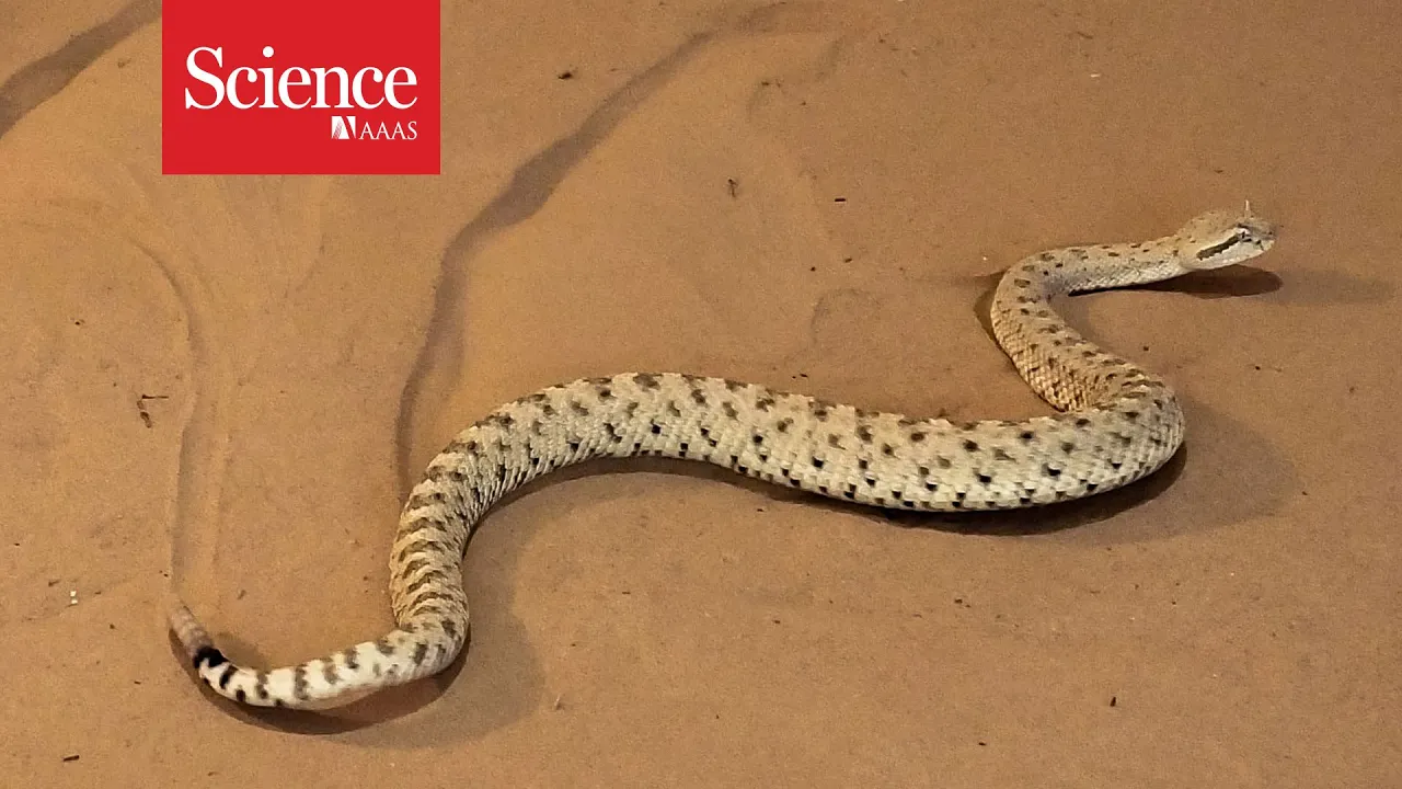
Why this video is valuable: This research video explains the physics of sidewinding in both biological snakes and robotic platforms. It demonstrates how sidewinding is generated by coordinating horizontal and vertical waves. This interaction determines which segments of the snake’s body press down to anchor it against the ground, while other segments lift and step laterally.

Why this video is valuable: This conference compilation showcases bioinspired robotics kinematics. It highlights how modular multi-joint configurations navigate uneven landscapes by shifting between horizontal (lateral) and vertical (dorsal) waves. This dual-wave coordination is the key to executing turns and navigating tight obstacles.
Mathematics & Code Implementation of Sidewinding
Note on Pool Gaps: Because there are no direct code walkthroughs for programming 3D sidewinding in the standard video pool, review and implement the mathematical concept detailed below:
Sidewinding requires a 3D snake body where segments alternate between horizontal joints (even indexes) and vertical joints (odd indexes).
Two waves are run simultaneously down the body:
Where is the phase difference between the vertical and horizontal waves (typically set to or radians). This phase shift coordinates the joint lifting: while a segment is flexing laterally, it is lifted vertically off the ground to clear friction, then placed back down to push off.
ESP32 Implementation Concept for Sidewinding:
To implement this in your code, loop through your servos and apply the respective wave equation based on whether the joint index is odd or even:
for (int i = 0; i < NUM_SERVOS; i++) { float targetAngle = 90.0; float t_phase = speed_coef * time_seconds + i * spatial_phase;
if (i % 2 == 0) { // Horizontal Joints targetAngle += amp_horizontal * sin(t_phase) + steering_offset; } else { // Vertical Joints targetAngle += amp_vertical * sin(t_phase + phase_shift_3d); }
pwm.setPWM(i, 0, angleToTicks(targetAngle)); }
Module 5 Knowledge Checkpoint
- Explain how vertical and horizontal waves interact to lift and anchor parts of a sidewinding snake robot.
- Program a phase shift () of exactly 90 degrees () between alternating vertical and horizontal joints.
- Implement a dynamic steering offset that allows you to turn the snake while maintaining a sidewinding gait.
- Test the snake robot on different surfaces, tuning amplitude ratios () to minimize slip.
Course Map
Key People Index
- Dr. Shigeo Hirose
- Context: Pioneer in biomechanics and robotic engineering. He was the first to model serpentine motion mathematically and introduced the Serpenoid Curve to robotics.
- Matthew Travers
- Context: Researcher at the Carnegie Mellon University (CMU) Biorobotics Lab. His team developed modular climbing snake robots (including the EELS project designed for extraterrestrial exploration).
- James Bruton
- Context: Renowned robotics designer and former toy developer. He provides invaluable open-source guides on mechanical assembly, linkage designs, and joint testing for multi-servo systems.
Final Self-Assessment
Perform this comprehensive final inspection to verify that your biomimetic snake robot is fully functional:
- Physical Check: All mechanical joints rotate smoothly through their range () without catching wires or hitting structural limits.
- Power Safety: The buck converter steps down battery voltage to a level safe for your servos (5V–6V) and does not warm up under active workloads.
- Signal Check: The ESP32 communicates with the PCA9685 over I2C without bus drops or logic resets when the servos start drawing current.
- Mathematical Modeling: You can explain the function of Amplitude (), Frequency (), and Spatial Phase () in the Serpenoid Curve.
- Symmetric Motion: Under lateral undulation, the snake’s joint positions trace out a clean sine wave when monitored on the Serial Plotter.
- Forward Undulation: The robot moves forward on a high-friction surface (like carpet) using lateral undulation.
- Steering Verification: The robot turns left and right when you write a non-zero steering offset value () to the joint equations.
- 3D Gait Execution: The robot sidewinds across flat terrain using alternating joint structures coordinated by perpendicular, phase-shifted waves.