STM32 Drone: DIY Assembly, PID & Sensor Fusion
Learning Goal: Assemble a custom quadcopter drone and program a flight controller from scratch on an STM32 microcontroller, implementing IMU sensor fusion and attitude PID control.
- Prerequisites: Intermediate C/C++ programming, basic embedded electronics knowledge (oscilloscopes, multimeter usage, schematic reading), and familiarity with microcontrollers.
- Estimated Total Study Time: 48 Hours
Module 1: Drone Hardware & Physics Foundations
Module Overview
To build a drone from scratch, you must first master the physics that govern its flight. This module covers the aerodynamical mechanics of lift, torque, pitch, roll, and yaw. You will also learn about key electronic hardware components—specifically, brushless DC (BLDC) motors, Electronic Speed Controllers (ESCs) that manage high-frequency phase commutation, and the 2.4GHz radio frequency (RF) protocol structures used to send command values from transmitter to receiver.
Recommended Videos
Video 1: Drones | The complete flight dynamics
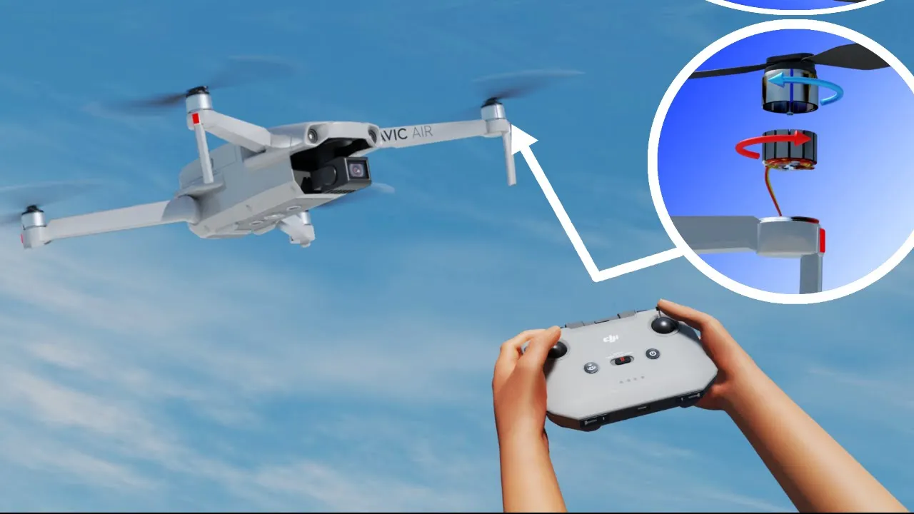
- Why this video: This video provides an intuitive breakdown of drone aerodynamics. It covers the airfoil principle of rotating blades, the cancellation of torque using counter-rotating propeller pairs (clockwise and counter-clockwise), and the exact motor differential thrust adjustments needed to execute pitch, roll, yaw, and translational flight.
- Knowledge Checkpoint:
- Explain how a quadcopter yaw's without altering its total lift.
- Describe the physical relationship between torque cancellation and the direction of motor rotation.
- Identify which motor pairs must accelerate or decelerate to execute a positive roll command.
Video 2: Intro to ESCs — Electronic Speed Controllers — Drone Doc Ep. 8
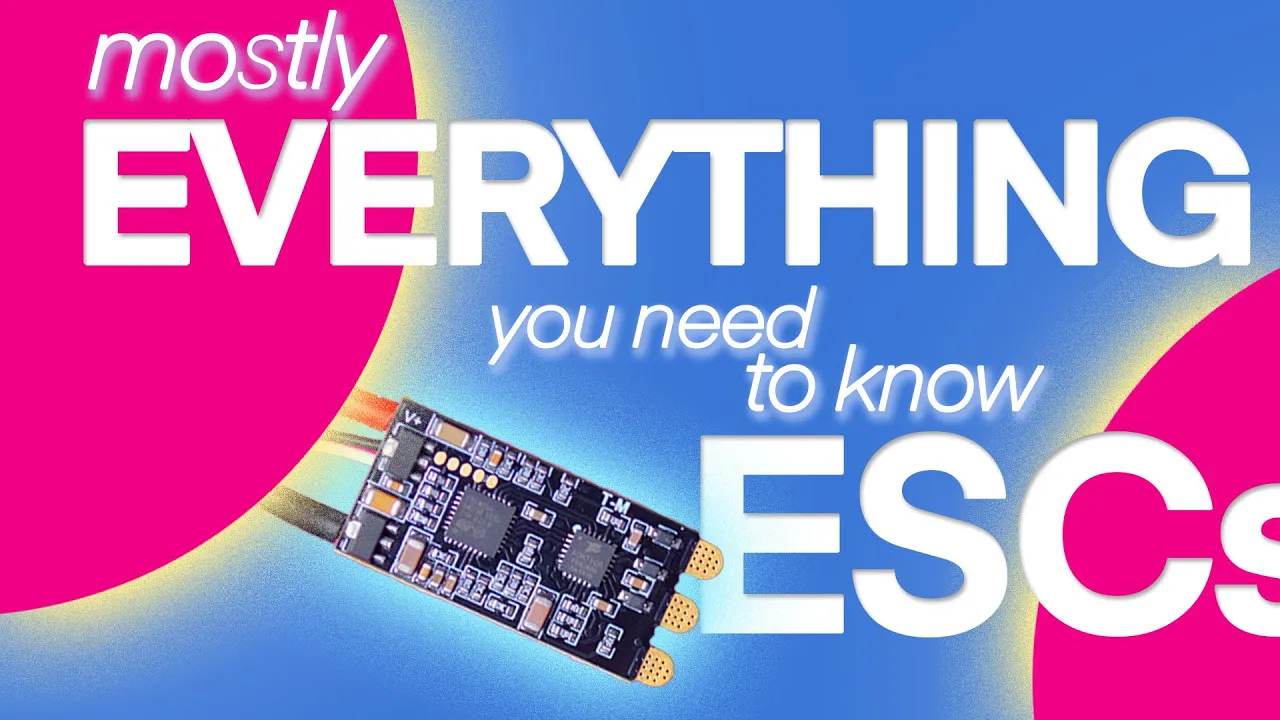
- Why this video: Your flight controller does not drive motors directly; it commands ESCs. This video explains how ESCs convert the direct current (DC) from LiPo batteries into high-amperage three-phase alternating current (AC) to drive brushless motors, highlighting the importance of current limits, motor KV ratings, and signal protocols.
- Knowledge Checkpoint:
- What is the main structural difference between brushed and brushless DC motors, and why do brushless motors require an ESC?
- Define the KV rating of a motor and explain how it influences propeller size selection.
- Why is a low-ESR capacitor soldered to the ESC power pads?
Video 3: RC Basics: Introduction to how a RC radio system works
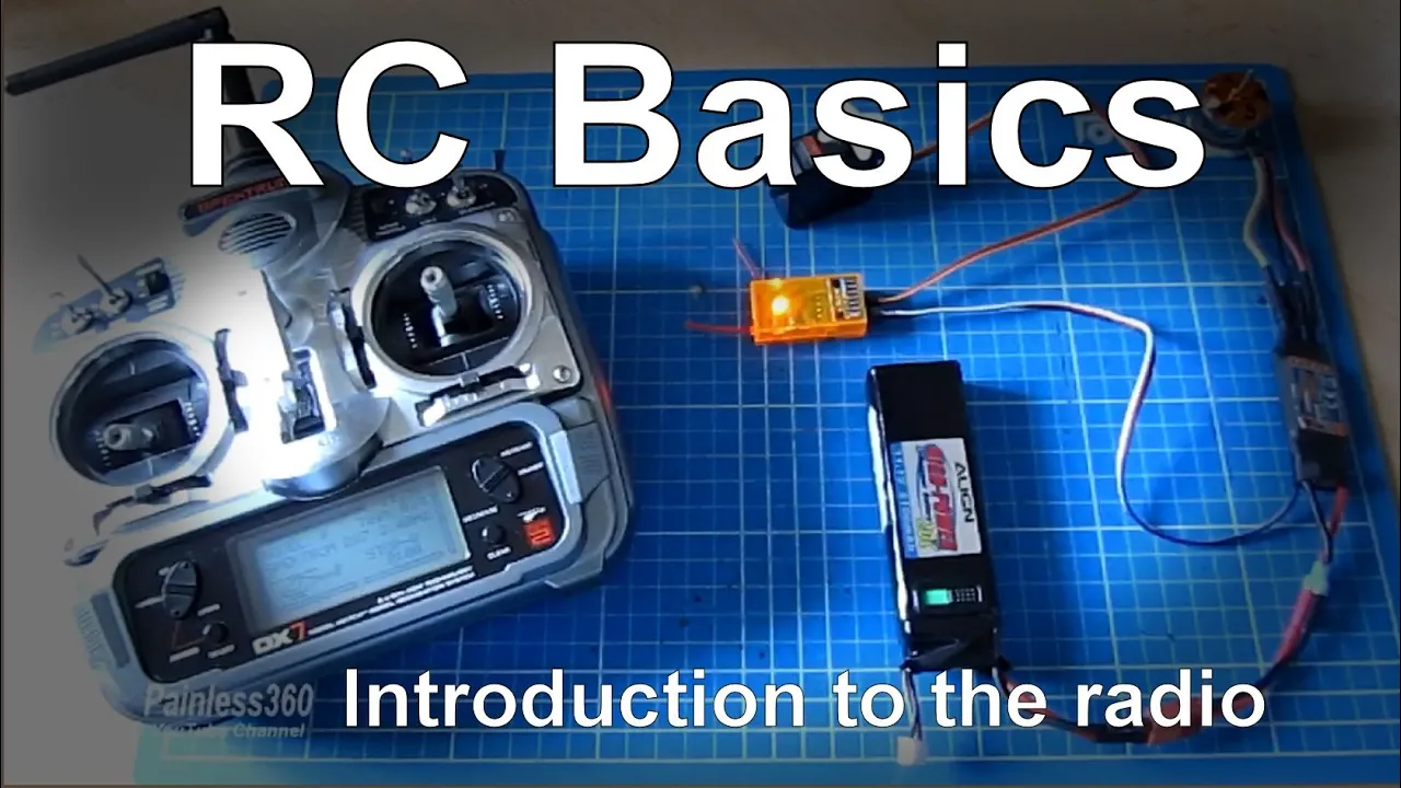
- Why this video: This deep dive covers the foundational elements of RC transmission. You will learn how control sticks translate physical movements into digital frames sent over the 2.4GHz spectrum, and how receivers convert those transmissions back into electrical control protocols.
- Knowledge Checkpoint:
- Describe the concept of channel mapping (e.g., TAER12 vs. AETR12).
- Explain the security mechanism of "binding" between a 2.4GHz transmitter and receiver.
- What occurs to receiver output pins when a "failsafe" event is triggered?
Module 2: STM32 Peripherals: Input Capture, UART & PWM
Module Overview
This module transitions your theoretical understanding into microcontroller operations. You will learn to configure an STM32 ARM Cortex-M processor to read receiver signals (using timer-based Input Capture interrupts or serial UART communication) and generate high-frequency PWM outputs to command ESCs.
Gap Note: While the video pool provides solid coverage of standard PWM generation and basic input capture timers, there is limited coverage on decoding complex digital serial protocols such as SBUS or IBUS on STM32 using DMA and IDLE-line interrupts. For physical builds utilizing serial receivers, independently search for:
"STM32 read SBUS receiver tutorial UART DMA".
Recommended Videos
Video 1: Starting with STM32 - Programming Tutorial for Beginners | Step by Step
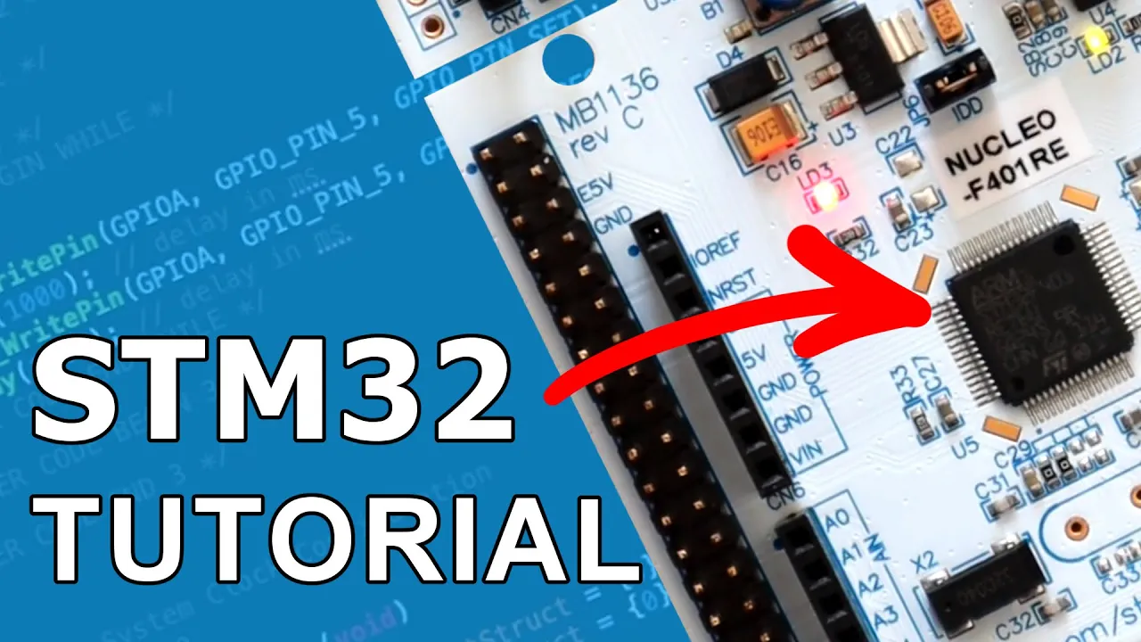
- Why this video: To program the flight controller, you need a firm grasp of the official development tool, STM32CubeIDE. This step-by-step masterclass covers creating projects, configuring clock trees, generating HAL initialization files, and understanding the main execution structure in code.
- Knowledge Checkpoint:
- Successfully generate an initialization template for an STM32 board using CubeMX inside CubeIDE.
- Describe the difference between the
HAL_GPIO_WritePinand raw register access instructions. - Explain the role of the system clock configuration (HCLK) when driving internal timer frequencies.
Video 2: Timer Peripheral Input Capture Mode in STM32
- Why this video: If you are reading traditional PWM/PPM signals from an RC receiver, you must use timer-based input capture to measure signal pulse widths accurately. This video explains how the STM32's internal timers latch their counter registers upon detecting signal edges (rising/falling).
- Knowledge Checkpoint:
- Configure an STM32 Timer channel to trigger an interrupt on both rising and falling edges.
- Write the mathematical logic to calculate pulse-width (in microseconds) using the captured counter differences.
- What causes a timer overflow error during input capture, and how do you prevent it?
Video 3: STM32 UART DMA and IDLE LINE || Receive unknown length DATA

- Why this video: Modern RC receivers output serial digital packets (like SBUS or IBUS) over a UART port instead of individual PWM lines. This tutorial is critical because it details how to set up UART with Direct Memory Access (DMA) and the IDLE Line interrupt to stream these serial packets directly into memory with zero CPU overhead.
- Knowledge Checkpoint:
- What is DMA, and why is it preferred over standard UART polling interrupts for high-rate data processing?
- Explain how an "IDLE Line" interrupt is triggered and how it helps parse serial frames of fluctuating lengths.
- Sketch a block diagram showing how data flows from receiver RX pin to STM32 RAM using UART DMA.
Video 4: STM32 Guide #4: Generated Code, HAL, and Bare Metal

- Why this video: You must generate precise PWM signals to drive your ESCs. This video provides a detailed breakdown of how STM32 timers create PWM signals, explaining how Prescalers (PSC), Auto-Reload Registers (ARR), and Capture Compare Registers (CCR) map directly to PWM frequency and duty cycle resolution.
- Knowledge Checkpoint:
- Calculate the required ARR and PSC values on a 72MHz clock to output a standard 400Hz PWM signal for your ESCs.
- Explain how varying the value in the CCR register changes the motor speed command.
- What is the physical duration difference between a 1000µs and a 2000µs pulse width in standard ESC control protocols?
Module 3: IMU Sensor Integration & Sensor Fusion
Module Overview
To maintain stable hover, a drone needs to know its orientation relative to the Earth. In this module, you will interface an MPU6050 Inertial Measurement Unit (IMU) with your STM32 using the I2C communication protocol. Because raw accelerometer data is incredibly noisy and raw gyroscope data drifts over time, you will implement a Complementary Filter or Kalman Filter to fuse these sensors into reliable roll and pitch values.
Gap Note: While the recommended videos explain I2C register configuration and sensor mathematics, there is a gap in detailed step-by-step C implementations of a Kalman filter specifically optimized for ARM microcontrollers. You should independently research:
"How to program complementary filter in C for IMU MPU6050".
Recommended Videos
Video 1: PART I: STM32 HAL I2C and MPU6050 IMU
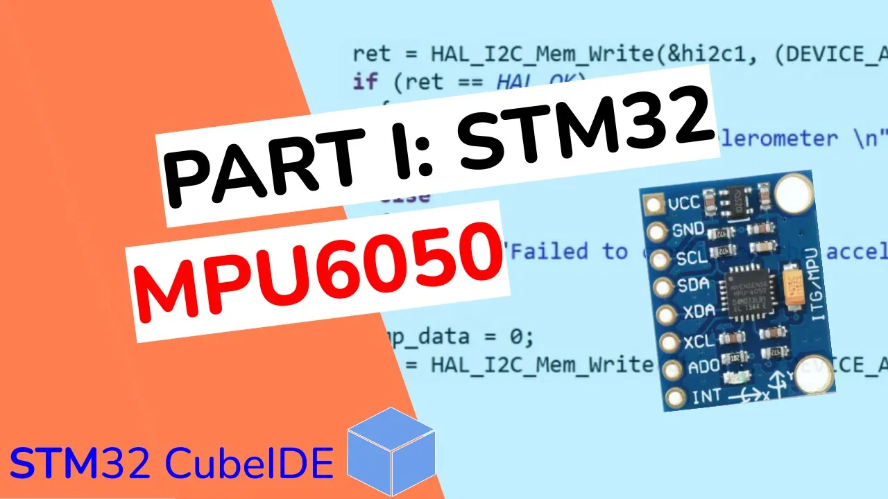
- Why this video: Before writing filtering algorithms, you must successfully read raw data from the IMU. This tutorial guides you through configuring STM32's I2C pins, querying the MPU6050’s register map, and retrieving raw accelerometer and gyroscope register values.
- Knowledge Checkpoint:
- Identify the MPU6050 I2C slave address and explain the significance of the "Who Am I" register (
0x75). - Read the accelerometer high and low 8-bit registers and combine them into a single signed 16-bit integer in C.
- Why must you configure the Gyroscope Full Scale Range register before translating raw ADC values into degrees per second?
- Identify the MPU6050 I2C slave address and explain the significance of the "Who Am I" register (
Video 2: Measuring Angles with MPU6050 Accelerometer for Quadcopter Stabilization
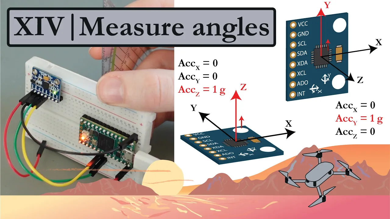
- Why this video: This video explains how to transform raw 3-axis accelerometer values into pitch and roll tilt angles using trigonometry. It highlights the physical limitations of relying solely on the accelerometer when the drone experiences high linear accelerations (vibrations from motors).
- Knowledge Checkpoint:
- Write the trigonometric formulas (using
atan2) used to calculate pitch and roll from 3-axis acceleration vectors. - Explain why motor vibrations introduce high-frequency noise in raw accelerometer angle calculations.
- Define 1G of acceleration in raw LSB values when the accelerometer scale is configured to ±2g.
- Write the trigonometric formulas (using
Video 3: Raspberry Pi Pico W LESSON 51: Ultimate Pitch and Roll Gadget Using the MPU6050

- Why this video: Though executed on an alternative MCU, this video offers an accessible visual explanation of a Complementary Filter. You will learn how the filter passes gyroscope integration through a high-pass path to prevent drift, while passing accelerometer raw tilt through a low-pass path to suppress vibration noise.
- Knowledge Checkpoint:
- Write the exact Complementary Filter equation used to calculate pitch: .
- What is the physical role of (sampling interval) in this equation, and why must it remain constant?
- How does changing the value of the filter coefficient (, e.g., 0.98 vs 0.90) affect response delay and noise attenuation?
Module 4: PID Flight Control Theory
Module Overview
With stable angle measurements, the flight controller must constantly issue motor corrections to eliminate the error between the pilot's desired angle and the drone's actual angle. This module introduces the Proportional-Integral-Derivative (PID) control algorithm, exploring loop frequency timing, mathematical term operations, anti-windup safety parameters, and systematic tuning strategies.
Recommended Videos
Video 1: The Importance of: PD Balance | P&D Gain Strength

- Why this video: This drone-focused analysis explains how the Proportional (P) and Derivative (D) terms interact in flight control. You will learn how the P gain drives motor response based on the absolute error, and how the D gain acts as a dynamic brake, dampening high-frequency oscillations to prevent overshooting.
- Knowledge Checkpoint:
- Describe the physical manifestation of "too much Proportional gain" vs. "too much Derivative gain" on a physical quadcopter frame.
- Why does increasing D gain help clean up overshoot during rapid roll maneuvers?
- What is the risk of excessive D gain relative to motor temperatures and electrical high-frequency noise amplification?
Video 2: Arduino PID Controller - From Scratch!

- Why this video: Implementing a controller requires translating math into robust C code. This walkthrough breaks down how a basic PID algorithm tracks elapsed execution time (), integrates errors over time, and calculates the rate of change of errors to output a unified control value.
- Knowledge Checkpoint:
- Implement the basic PID loop variables, error calculations, and accumulation terms in a C-style script.
- Explain "Integral Windup" and write a simple code block to cap (limit) the maximum cumulative value of your Integral term.
- Why is it dangerous to compute derivative terms without a small low-pass filter on the derivative input?
Video 3: 13 | This 170-line Arduino code is a drone flight controller
- Why this video: This video pulls conceptual elements together, walking you through a complete, bare-bones flight controller loop operating at a strict 250Hz frequency. It shows how RC receiver signals are converted into target target angular rates, compared to IMU gyroscope readings, and fed into three separate PID controllers (for Roll, Pitch, and Yaw).
- Knowledge Checkpoint:
- Define the exact sequence of actions that must occur within every iteration of the flight controller loop.
- Why does this flight controller loop compare receiver inputs directly to raw angular rates (degrees/second) from the gyroscope instead of raw Euler angles? (Hint: Rate Mode / Acro Mode vs. Attitude Mode).
- How is the precise loop frequency of 250Hz enforced in software?
Module 5: Drone Coding, Assembly, & Flight Testing
Module Overview
In this final integration phase, you will physically assemble your quadcopter (securing ESC connections, soldering power leads, and verifying motor orientation) and complete the STM32 firmware loop. You will implement a motor mixing matrix that combines the PID controller outputs into signals for the four independent ESC channels, verify safety failsafes, and execute your first indoor or tethered flight safely.
Gap Note: Writing a functional motor mixer requires transforming PID pitch, roll, and yaw outputs into localized ESC values. Because specific mixing code is rare in standard tutorial pools, search independently for:
"Quadcopter motor mixing algorithm PID implementation C code".
Recommended Videos
Video 1: 2022 Freestyle FPV Drone Build (DIY Kit For Total Beginners)

- Why this video: A successful project relies on physical structural integrity. This video covers frame component assembly, soldering high-amperage power leads safely, mounting the motors securely, and checking for common electrical hazards like carbon fiber continuity shorts.
- Knowledge Checkpoint:
- Correctly mount and torque the motors, ensuring mounting screws do not pierce or contact internal stator copper windings.
- Perform a continuity check between your main battery leads and the carbon fiber frame using a digital multimeter.
- Describe the correct physical configuration of props-in vs. props-out rotational directions.
Video 2: Stm32f103 , hack fly controller
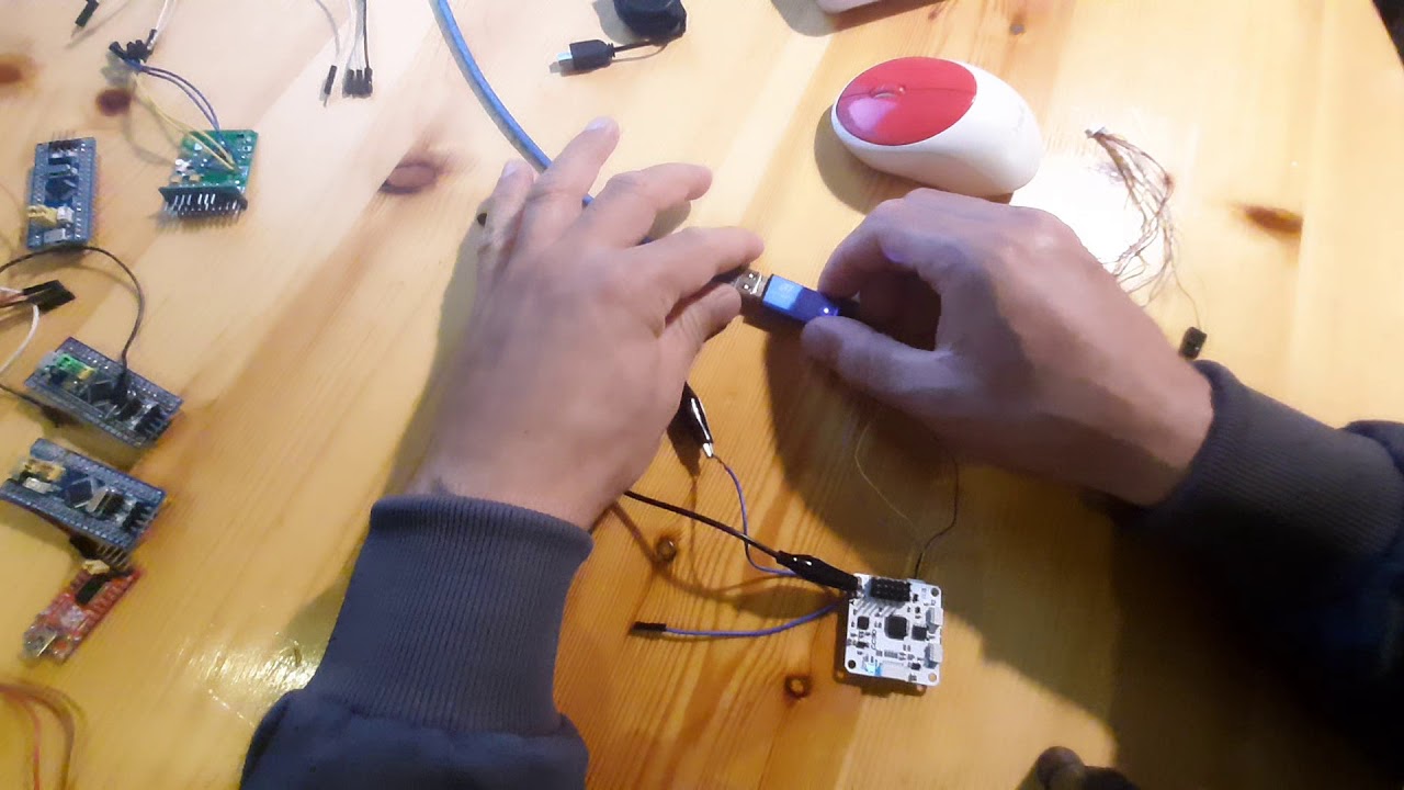
- Why this video: This video focuses on hardware integration. It shows how an STM32 development board (such as the Blue Pill STM32F103) is wired directly to an IMU, receiver pins, and ESC signal wires, creating a fully functioning, custom-fabricated flight controller.
- Knowledge Checkpoint:
- Map the physical pinouts of your STM32 to the custom firmware pins defined in your project (I2C1 SCL/SDA, TIM1 PWM channels, Receiver USART pins).
- Describe the voltage regulation requirements when powering an STM32 microcontroller and receiver from a high-voltage LiPo flight battery (e.g., using a 5V BEC).
- Identify debugging communication lines (SWD interface) required to flash your custom binaries directly to the STM32 board.
Video 3: Learn To Build a Racing Drone - Part 15 - First Hover
- Why this video: The final stage requires extreme safety. This tutorial outlines the exact procedures for a "maiden" flight, covering how to perform motor tests on the bench with propellers off, checking receiver controls visually, and conducting safe initial hover tests to look for over-oscillations.
- Knowledge Checkpoint:
- Complete a pre-flight test sequence: verifying motor rotation directions, proper control axis responses, and failsafe shut-offs (always with propellers removed).
- Explain how to verify that the attitude correction feedback loop is working in the correct direction (i.e., when you tilt the drone physically, does it spin up the correct motor to resist that tilt?).
- Describe how to safely react if the drone experiences immediate takeoff flyaway or violent oscillations (e.g., proper disarm procedures).
Course Map
Key People Index
- Joshua Bardwell (@JoshuaBardwell): A world-renowned master educator on custom multirotor flight controller configurations, analog/digital RF transmission systems, physical hardware assembly, and flight safety diagnostics.
- UAVtech (@uavtech): A prominent developer and analyst specializing in flight dynamics, dynamic filtering algorithms, blackbox logging analysis, and the intricacies of PID loop balance tuning.
- Paul McWhorter (@paulmcwhorter): An expert engineering educator focused on making embedded systems programming, sensor data translation, and basic classical filtering logic intuitive.
- Carbon Aeronautics (@carbonaeronautics): A mechanical and software engineer dedicated to building, coding, and tuning lightweight multirotor aircraft using open-source tools and microcontrollers.
Final Self-Assessment
Execute this final integration assessment with your fully compiled STM32 custom flight controller and assembled quadcopter.
Safety Warning: Remove all propellers before performing any electrical, coding, or transmitter tests. Only mount propellers once every check below is passed.
- I2C Signal Health: The STM32 successfully reads 3-axis accelerometer and 3-axis gyroscope data from the MPU6050 over I2C, with zero communication lockups during bench testing.
- Sensor Fusion Calibration: Pitch and roll outputs calculated from the sensor fusion filter read exactly 0.0° when the quadcopter is resting on a level surface, and follow physical hand tilts with minimal delay and no angular drift over a 5-minute period.
- Receiver Integration: In the debugging terminal, receiver control signals read exactly 1000µs (minimum), 1500µs (neutral), and 2000µs (maximum) for all active pitch, roll, yaw, and throttle channels.
- Failsafe Verification: If the transmitter is powered off, the STM32 instantly detects the loss of receiver signal and sets all motor outputs to 0 (minimum throttle) within less than 200 milliseconds.
- Attitude Response Direction: With propellers off, tilting the drone physically forward causes the front motors to accelerate and the rear motors to decelerate to resist the motion.
- Strict Execution Timing: The core loop (reading inputs, running sensor fusion, executing PID algorithms, and updating motor PWM outputs) runs at a highly precise frequency (e.g., 250Hz or 500Hz) with jitter of less than 2%.
- Hardware Continuity Check: A digital multimeter shows infinite resistance (no continuity) between positive/ground battery leads and all parts of the conductive carbon fiber frame.
- Successful Hover Maiden: The quadcopter executes a stable hover within a limited altitude window (e.g., 2-3 feet) during its first outdoor flight, with no signs of violent over-oscillations or runaway behavior.