Self-Balancing Robots: Arduino & PID Control
Learning Goal: Design, build, and program a self-balancing two-wheeled robot using Arduino and PID control algorithms.
Welcome to this comprehensive hands-on curriculum. By the end of this course, you will understand the fundamentals of control theory, design mechanical balancing platforms, build clean power distribution systems with LiPo protection circuits, interface with Inertial Measurement Units (IMUs), and tune Proportional-Integral-Derivative (PID) algorithms to stabilize an inverted pendulum chassis.
- Prerequisites: Basic knowledge of electrical concepts (voltage, current, resistance) and introductory exposure to programming concepts (variables, loops). No prior control theory or robotics experience is required.
- Estimated Total Study Time: 50 Hours
Module 1: Arduino & Basic Electronics Foundations
This module builds the absolute foundational skills needed to interact with microcontrollers, write C++ programs in the Arduino IDE, and leverage Pulse Width Modulation (PWM) to regulate electrical power delivery.
Module Overview
You will learn to navigate the physical pinout of an Arduino Uno/Nano, interface with a breadboard, and write basic hardware control code. A key objective here is mastering Pulse Width Modulation (PWM), which is the primary mechanism our microcontroller uses to simulate an analog voltage output to motor drivers.
Recommended Videos

Why this video:
This deep-dive masterclass provides the perfect zero-to-hero introduction to the Arduino IDE and C++ syntax. It focuses extensively on crucial syntax elements, hardware configuration, and standard functions like analogWrite(), which is used to output PWM signals to control motor speeds.

Why this video: This highly visual guide breaks down the core mechanics of Pulse Width Modulation (PWM). You will learn how microcontrollers transition between digital states to generate average voltages, allowing you to manipulate the duty cycle and scale the power delivered to external actuators.

Why this video: Standard Arduino PWM frequencies (490Hz to 976Hz) can cause an audible, high-pitched whine when driving DC motors. This video demonstrates the mechanics of Arduino hardware timers and shows how to adjust PWM frequency to optimize motor driver responsiveness and eliminate annoying acoustic noise.
Knowledge Checkpoint
- Write, compile, and upload an Arduino script that utilizes
analogWrite()to sweep the brightness of an LED. - Explain how a 50% duty cycle on a 5V digital pin translates to an average output of 2.5V.
- Identify which pins on the Arduino Uno support hardware PWM out of the box (hint: look for the tilde
~symbol). - Understand the role of internal microchip timers (Timer 0, Timer 1, Timer 2) in generating PWM frequencies.
Module 2: Sensors and Actuators: IMUs and DC Motors
This module transitions from basic electronics to the core inputs and outputs of our self-balancing robot: the Inertial Measurement Unit (IMU) and DC geared motors.
Module Overview
To maintain balance, your robot must know its exact tilt angle in real-time and react immediately with motor corrections. You will learn to interface with the MPU6050 accelerometer and gyroscope, understand the differences between linear acceleration and angular velocity, and master the math of sensor fusion. Additionally, you will write code to command high-torque DC motors using an H-bridge driver.
Recommended Videos
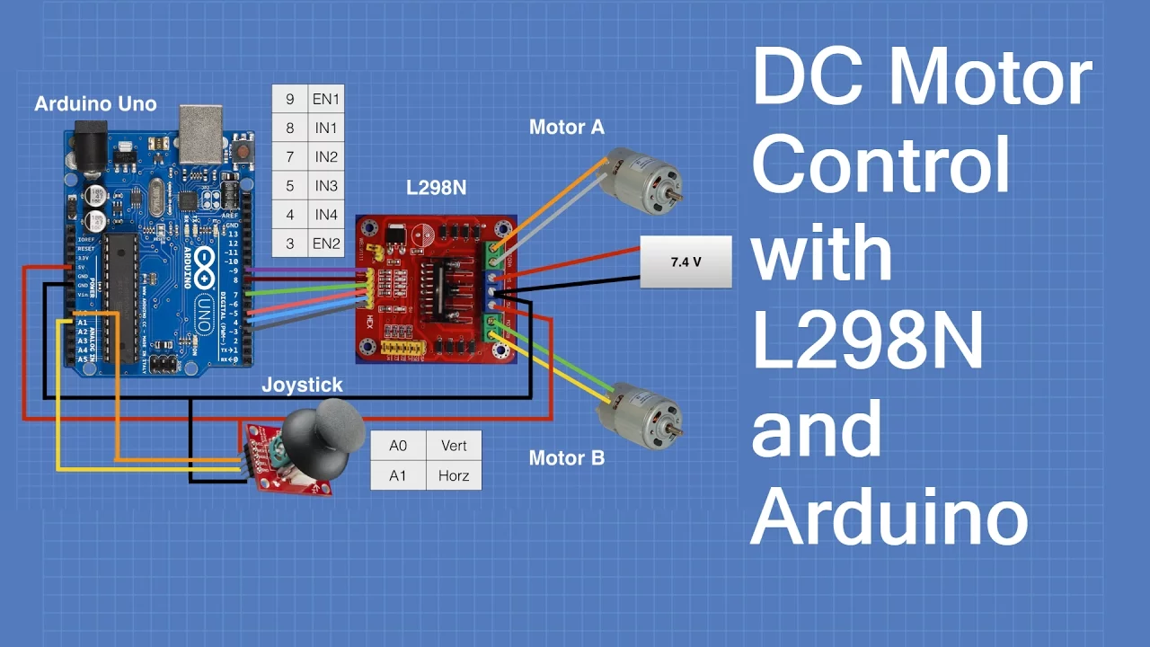
Why this video: The L298N dual H-bridge motor driver is standard for driving robotic wheels. This detailed tutorial breaks down hardware connections, H-bridge internal switching logic, and how to program direction control using digital pins and speed control using PWM signals.
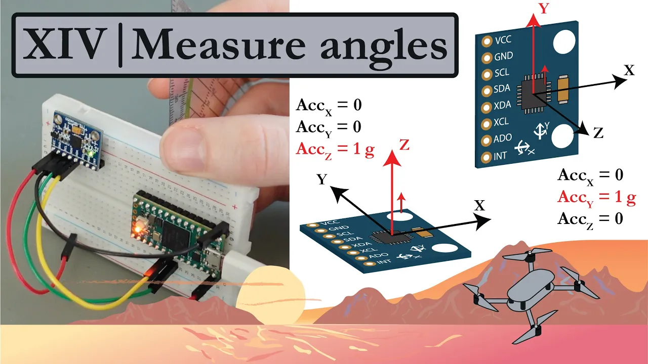
Why this video: This tutorial explains the raw physics of calculating tilt angles from an accelerometer. It covers trigonometry using gravity vectors (1G) and details how mechanical vibrations can distort raw accelerometer readings.
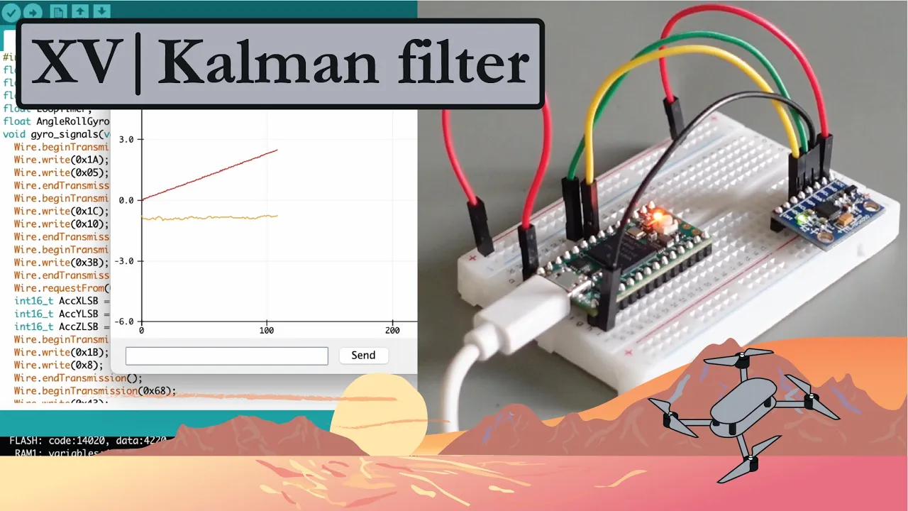
Why this video: A gyroscope drifts over time, while an accelerometer is noisy under vibration. This video introduces sensor fusion, teaching you to combine both sensors using a Complementary or Kalman filter to calculate an accurate, drift-free, real-time pitch angle.

Why this video:
Every MPU6050 chip has slight manufacturing variations that lead to sensor offset. This video details how to write a simple calibration script to calculate and apply gyro offsets, ensuring the robot reads exactly 0.0 degrees when perfectly upright.
Knowledge Checkpoint
- Explain how an H-bridge controls motor direction by reversing voltage polarity.
- Connect an L298N driver to an Arduino and write a script to spin a motor clockwise and counterclockwise at varying speeds.
- Calculate a raw angle estimate from accelerometer readings, and explain why high-frequency vibrations disrupt it.
- Describe how a complementary filter combines the low-frequency stability of an accelerometer with the high-frequency tracking of a gyroscope.
Module 3: PID Control Theory and the Inverted Pendulum
This module explores the mathematics and intuition behind closed-loop feedback systems.
Module Overview
A self-balancing robot is a physical implementation of an inverted pendulum on wheels—an inherently unstable system. To keep it upright, we use a Proportional-Integral-Derivative (PID) controller. This module breaks down the mathematical contribution of each term (, , and ) and how they work together to stabilize the robot.
Recommended Videos
![Inverted Pendulum on a Cart [Control Bootcamp]](https://i.ytimg.com/vi/qjhAAQexzLg/maxresdefault.jpg)
Why this video: Steve Brunton provides an intuitive, mathematically rigorous overview of the classic inverted pendulum on a cart. This video connects physical equations of motion to control theory, helping you understand how adjusting wheel acceleration stabilizes a falling body.

Why this video: This structural breakdown of a PID controller uses block diagrams to show how the current error, integrated historical error, and predicted derivative error combine to generate a cohesive control output.

Why this video: This tutorial covers the Ziegler-Nichols method, a classic heuristic technique for tuning PID loops. Understanding how to find the ultimate gain () and period of oscillation () provides a solid foundation for manual tuning strategies.
Knowledge Checkpoint
- Define what "Error" represents in a self-balancing robot (Hint: Target Angle vs. Current Angle).
- Explain why a proportional-only () controller will always overshoot or fail to stabilize an unstable system.
- Describe the dampening effect of the Derivative () term and how it prevents wild oscillations.
- Draw a PID feedback loop block diagram showing input (Set Point), Process Variable (IMU Tilt), Controller (Arduino), Actuator (Motors), and Feedback.
Module 4: Robot Mechanical Assembly & Power Systems
This module focuses on physical construction and the power systems needed to safely run high-current motors alongside a sensitive microcontroller.
Module Overview
A self-balancing robot requires careful mechanical design and clean power distribution. You will learn to construct a physical chassis, position components to optimize the center of gravity (CoG), and wire high-drain Lithium Polymer (LiPo) batteries.
Critical Power Safety & Battery Management (Addressing Curricular Gaps)
The video pool has a distinct lack of safety-focused content on LiPo batteries, power distribution, and voltage regulation. To address this, please study this comprehensive technical guide before beginning assembly:
1. The Multi-Cell LiPo Hazard
LiPo batteries are power-dense but chemically unstable if mistreated. A 2S (7.4V nominal / 8.4V peak) or 3S (11.1V nominal / 12.6V peak) battery pack is ideal for self-balancing robots.
- Over-Discharge Ruin: If any single cell drops below 3.0V (or 6.0V total for 2S, 9.0V total for 3S), the chemistry permanently breaks down. The battery will swell ("puff") and can catch fire on a subsequent charge.
- Over-Current Draw: Drawing more current than the battery's discharge rating ("C-rating") can cause catastrophic thermal runaway.
2. Isolation of Noise and Voltage Planes
Never run your Arduino from the exact same un-isolated voltage rail that feeds raw power to high-current DC motor drivers. When motors kick on, they draw high surge currents that cause massive voltage drops, while motor commutators feed electromagnetic noise back into the lines. This will cause your Arduino to brown out, freeze, or experience sensor errors.
-
The Dual-Rail Solution: Connect the battery directly to the L298N Motor Driver input pin (). Run a separate, tap-off line from the battery into an LM2596 buck converter or similar high-efficiency step-down switching regulator. Output a constant, regulated 7.0V to 9.0V into the Arduino's barrel jack or
VINpin (or a clean 5V directly into the pin). This keeps your logic circuit shielded from motor-induced voltage sags.+-----------------------+ | LiPo Battery (7.4V) | +---+---------------+---+ | | (High Current) | (Low Current Logic) v v +--------+--------+ +---+------------+ | L298N Motor | | LM2596 Buck | | Driver Board | | Step-Down (5V) | +--------+--------+ +---+------------+ | | v v [DC Motors] +----+----+ | Arduino | +----+----+ | (I2C) v [MPU6050]
3. Designing a Safe Undervoltage Protection Program (Voltage Divider Setup)
You must build a simple physical hardware voltage sensor on the robot so the Arduino can monitor battery level and cut motor power when it gets low:
- Wire a basic voltage divider: Connect the battery positive terminal through a resistor to the Arduino Analog pin . Connect through a resistor to Ground.
- This drops a 12.6V maximum voltage down to a safe , which is well within the safe limit of the analog input pin.
- In your loop, check this value continuously:
float batteryVoltage = analogRead(A0) * (5.0 / 1023.0) * ((100000.0 + 10000.0) / 10000.0);
if (batteryVoltage < 6.4) { // Threshold for 2S LiPo
    // IMMEDIATELY halt all DC motors to protect the battery and prevent crashes
    digitalWrite(motorLeftEnable, LOW);
    digitalWrite(motorRightEnable, LOW);
    while(1) { /* Infinite halt loop with buzzer alarm */ }
}
Recommended Videos

Why this video: This step-by-step physical assembly guide shows how to cut, drill, stack, and secure a multi-tier chassis. You will see how to arrange the heavy battery pack, DC gear motors, breadboard, and sensor array to balance the platform's physical structure.
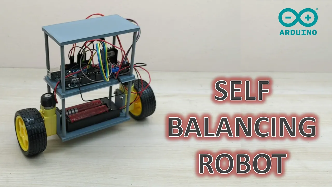
Why this video: This video focuses on wiring the platform, showing how to connect an Arduino Uno, L298N driver, and MPU6050 on a tight, vertical chassis.
Knowledge Checkpoint
- Construct a multi-tier self-balancing robot chassis, placing the MPU6050 sensor as close to the wheel axle axis as possible.
- Implement a 2S or 3S LiPo battery power system with a dedicated step-down buck converter to protect the Arduino's logic rail from motor-induced voltage drops.
- Calculate the expected output of your voltage divider when your battery is fully charged vs. near-empty, and map this to the analog input scale.
- Write a safety test script that lights a warning LED and disables motor outputs if battery voltage falls below per cell.
Module 5: Programming and Tuning the Robot
This module pulls everything together: merging sensor readings, the PID control loop, motor commands, and power monitoring into a single, cohesive codebase.
Module Overview
You will write the main control loop, calibrate your sensors, and implement a systematic PID tuning strategy. Since tuning a physical self-balancing robot is highly dynamic, this section provides step-by-step, practical procedures to transition your system from a violent, oscillating mess into a rock-solid, self-stabilizing machine.
Manual PID Tuning Protocol (Addressing Curricular Gaps)
Tuning a self-balancing robot requires a systematic, iterative approach. Follow this step-by-step protocol to manually find your , , and parameters:
Step 1: Establish Your Baseline
- Set all three gains to zero: , , .
- Hold your robot upright, power it on, and verify that the motors remain completely still when the robot is held at its zero-tilt point.
Step 2: Tune the Proportional Gain ()
- provides the corrective force to counter gravity. Too low, and the robot won't try to stand. Too high, and it will violently shake.
- Start by setting a very low value (e.g., ).
- Double iteratively (e.g., 5, 10, 20...) until the robot begins to actively respond to falls, moving the wheels in the direction of the lean.
- Keep increasing until the robot overcorrects, resulting in a continuous, steady back-and-forth oscillation. Once you achieve this steady, self-sustained oscillation, note this value as your critical proportional gain ().
- Set your operating to approximately of this value (). At this point, the robot will respond to falls but will still slowly fall over due to a lack of damping.
Step 3: Tune the Derivative Gain ()
- acts as a damper, predicting future motion and countering rapid changes in tilt. It dampens the oscillations introduced by .
- Begin adding in small increments (e.g., start at , then increase).
- You will notice that as increases, the back-and-forth oscillation decreases.
- Keep increasing until the robot stays upright when given a gentle push, settling back into place without oscillating. If is too high, the robot will make rapid, jittery movements and sound like it is buzzing.
Step 4: Tune the Integral Gain ()
- corrects steady-state error. Over time, friction and slight imbalances will cause your robot to drift slowly in one direction, leaning slightly forward or backward without returning to true center.
- Introduce a very small value (e.g., ).
- The integral term accumulates the persistent tilt error and slowly drives the motors harder to bring the robot back to true center.
- Keep as low as possible. If is too high, the robot will drift in slow, growing waves until it loses balance entirely.
Recommended Videos
Why this video: This concise guide walks you through the physical effects of adjusting , , and gains on a physical two-wheeled chassis, serving as a quick reference during the tuning process.
Why this video: This video walks through writing the integration code for a self-balancing robot. You will see how sensor input, the PID calculations, and motor output functions are nested together in the main control loop.

Why this video: James Bruton explains an interesting concept: taller robots fall slower because of their greater rotational inertia. This video details how a robot's height affects tuning, and why a high integral gain combined with low derivative gain works well for taller structures.
Why this video: This video provides a great demonstration of a completed robot, highlighting how high proportional values help it accelerate quickly to stay under its center of gravity.
Knowledge Checkpoint
- Assemble the complete integrated codebase on your Arduino.
- Implement a strict timer loop in your code to ensure the PID loop executes at a highly consistent rate (e.g., exactly every 10 milliseconds).
- Manually tune your robot using the step-by-step protocol until it stands stable and resists gentle bumps.
- Diagnose issues: Identify whether a persistent wobble is caused by an over-tuned , under-tuned , or an overly aggressive .
Course Map
This map outlines the recommended learning progression and dependency path across the modules.
Key People Index
Notable creators and control theorists highlighted in this curriculum:
- Dr. Steve Brunton (@Eigensteve): Professor of Applied Mathematics and Mechanical Engineering at the University of Washington. His "Control Bootcamp" series is an outstanding resource for translating classical feedback control theory into intuitive physical implementations.
- James Bruton (@jamesbruton): Former toy designer and electrical/robotics engineer. His experimental robotics builds provide highly accessible, real-world demonstrations of PID, mechanical design, and physical tuning concepts.
- Julian Ilett (@JulianIlett): Hardware hacker and electronics educator. His deep-dive experiments with Arduino timers and PWM frequencies are invaluable for custom motor controller designs.
Final Self-Assessment
Complete this comprehensive checklist to confirm your self-balancing robot is fully functional, safe, and robust:
- I2C Communication: The Arduino successfully initializes and communicates with the MPU6050 sensor over I2C, with zero connection drops.
- Sensor Calibration: When placed on a flat, level surface, the calibrated IMU output reads exactly degrees for pitch.
- Sensor Fusion: The calculated tilt angle remains accurate, drift-free, and unaffected by high-frequency motor vibrations when holding the robot.
- Motor Response Verification: Tilted forward, the wheels drive forward; tilted backward, the wheels drive backward.
- Active Power Regulation: The logic circuits (Arduino and IMU) run on a dedicated regulator, separate from the high-current motor power rails.
- LiPo Over-Discharge Protection: A physical voltage divider is wired to an analog pin, and the code shuts down motor outputs if the cell voltage drops below a safe threshold.
- Strict PID Loop Timing: The main control loop runs at a fixed, consistent interval (e.g., or delta-T).
- Successful Proportional Stabilization (): The proportional gain is set high enough to generate immediate correction, but low enough to avoid violent shaking.
- Successful Derivative Damping (): The derivative term is tuned to eliminate continuous rocking, allowing the robot to settle quickly.
- Steady-State Error Correction (): The integral term is tuned to correct slow drifts, keeping the robot balanced in one place.
- Robustness Validation: The robot remains standing on two wheels for at least 5 minutes and can recover its balance when gently pushed from either direction.