ESP32 Quadruped: Build, Gait & Web Control
Learning Goal: Build and program a 4-legged (quadruped) robot using ESP32 to achieve stable gait generation and remote control via a custom web interface.
- Prerequisites: Basic familiarity with the Arduino IDE (C++ programming), fundamental physics/trigonometry concepts (coordinate systems, cosines), and basic HTML/CSS/JavaScript.
- Estimated Total Study Time: 35 Hours
Module 1: Introduction to ESP32 and Servo Control
This module establishes the foundational hardware and software skills required to work with the ESP32 microcontroller and high-torque servo motors. You will learn how the ESP32 handles complex tasks compared to standard Arduino microcontrollers, configure its development environment, and master pulse-width modulation (PWM) to safely drive multiple servos without damaging your board.
Recommended Videos
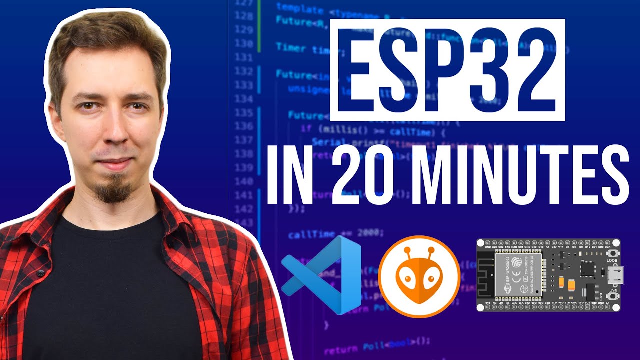
Why this video: This step-by-step tutorial is essential for setting up the ESP32 development workflow. It guides you through installing USB-to-UART bridge drivers, configuring the board manager within the Arduino IDE, and debugging initial test scripts. Correct environment setup is vital to avoid connection or flashing issues later in the build.

Why this video: Transitioning from 8-bit controllers (like the Arduino Uno) to the dual-core, 240MHz 32-bit ESP32 is a major architectural step up. This technical overview clarifies the hardware advantages of the ESP32—such as integrated Wi-Fi, Bluetooth, and dedicated PWM hardware—which are critical for processing kinematics and remote control commands simultaneously.
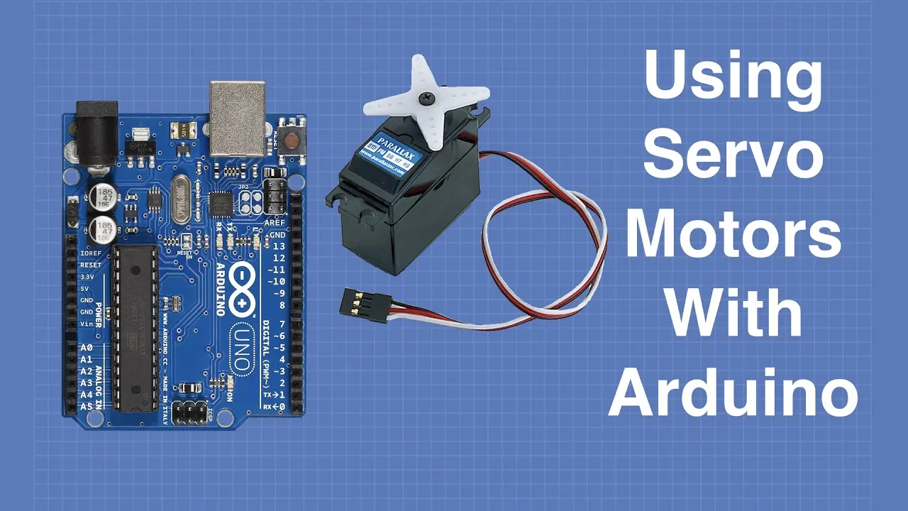
Why this video: Servo motors are the muscles of your quadruped robot. This comprehensive guide covers the physics of servos, internal gear systems, and the precise timing of PWM signals (where a 1.5ms pulse centers the servo at 90 degrees). Crucially, it highlights power management rules, detailing why you cannot safely power multiple mechanical motors directly from the microcontroller's 5V rail.
Knowledge Checkpoint
- Install the CP210x or CH340 USB drivers and successfully upload a test sketch to your ESP32.
- Explain why the ESP32 is better suited for real-time robotic gait engines than standard 8-bit Arduino boards.
- Define the timing parameters of a standard hobby servo PWM signal (frequency, period, and pulse width range).
- Diagram a safe power distribution circuit that isolates the high-current demands of servos from the ESP32 logic pins.
Module 2: Quadruped Mechanics and Hardware Assembly
This module covers the physical structure of 8-DOF (Degrees of Freedom) and 12-DOF robots, detailing how to translate 3D-printed assemblies into operational mechanical limbs. You will learn to integrate the PCA9685 16-channel PWM servo driver via the I2C bus to manage all your joints through a single serial bus, and perform software-based calibration to home the legs accurately.
Recommended Videos
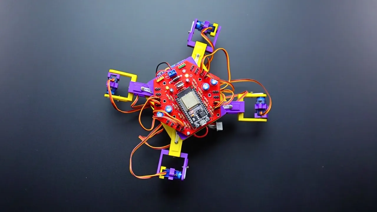
Why this video: This project breakdown demonstrates how to organize 3D-printed chassis plates, leg connectors, and servo holders into a functional 4-legged assembly. It highlights structural load considerations and physical component alignment, helping you understand how joint segments interact to support the weight of the battery and controller.
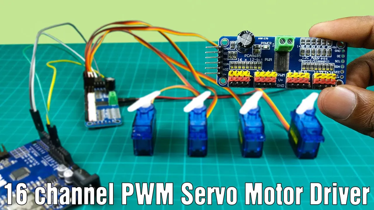
Why this video: A quadruped requires at least 8 to 12 servos, which can quickly exhaust the ESP32’s native GPIO pins and processing loops. This tutorial teaches you how to wire and program the PCA9685 PWM driver over I2C, offloading timing-sensitive PWM generation from the main CPU.
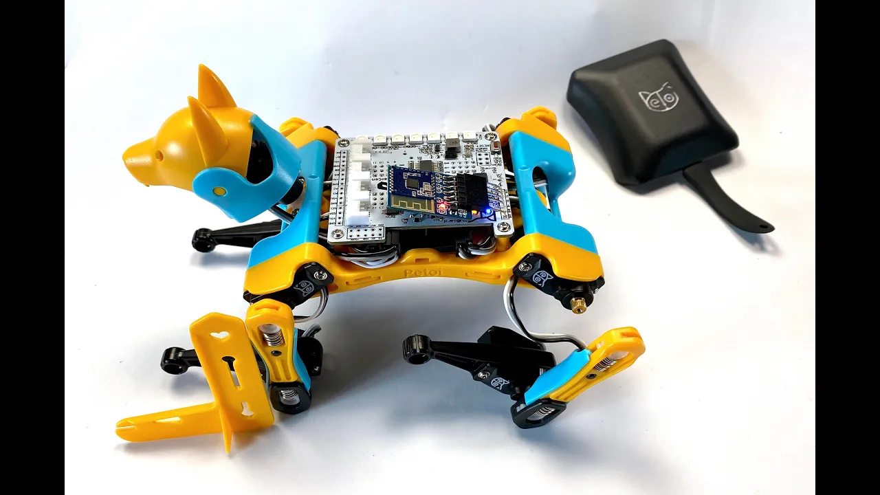
Why this video: Even a perfectly assembled robot will fail to walk if its joints are uncalibrated. Using the commercial Petoi Bittle as a reference, this guide demonstrates the critical step of software calibration. You will learn how to align physical servo horns to precise neutral resting angles and use software offsets to correct for physical misalignment.
Curriculum Note on Hardware Gaps: Because custom 3D-printed quadruped frames vary wildly, you should supplement this module by searching for the assembly instructions specific to your chassis (such as "SpotMicro assembly" or "Mini K開er assembly"). Always print chassis structural parts with at least 3-4 perimeters and 25%+ infill to prevent the joint mounts from flexing under load.
Knowledge Checkpoint
- Assemble the 4-legged chassis, securing all servo horns perpendicularly relative to their respective limb links.
- Connect the PCA9685 to the ESP32 via SCL (GPIO 22) and SDA (GPIO 21) pins and verify the I2C address.
- Write an Arduino sketch that uses the Adafruit PCA9685 library to command a servo to sweep smoothly.
- Implement a calibration configuration file in your code to store pulse offset values for each joint, ensuring the legs align perfectly parallel and perpendicular to the chassis when homed.
Module 3: Leg Kinematics and Gait Theory
This module focuses on the mathematical principles behind legged movement. To move a foot to a specific point in space, you must calculate the exact angles for each joint—a process called Inverse Kinematics (IK). You will study 2-DOF and 3-DOF leg trigonometry and examine the structural differences between a stable crawl gait and a dynamic trot gait.
Recommended Videos

Why this video: This academic lecture explains the geometry of 2-DOF and 3-DOF robotic linkages. It walks you through solving the Law of Cosines to determine joint angles (, ) from desired () foot coordinates, providing the mathematical foundation for your walking engine.

Why this video: James Bruton shows how abstract trigonometric IK formulas translate to physical code on a legged robot. He explains how to map 3D coordinate inputs () to coordinate systems relative to each leg's shoulder joint, demonstrating kinematic modeling in action.

Why this video: This video demonstrates the implementation of a crawl gait on a physical quadruped. It explains how to program leg movements to follow an elliptical coordinate path, showing how stable walk sequences require keeping three feet on the ground at all times.

Why this video: A trot gait is faster and more dynamic than a crawl, moving diagonal pairs of legs together. This video analyzes how diagonal legs contact the ground simultaneously, illustrating the mechanics of dynamic balance.
Knowledge Checkpoint
- Draw a 2D vector diagram of a 2-DOF robotic leg and derive the algebraic equations for the joint angles using the Law of Cosines.
- Explain the difference between Forward Kinematics (FK) and Inverse Kinematics (IK).
- Define the timing phase differences and support-polygon rules between a static crawl gait (3-point contact) and a dynamic trot gait (2-point contact).
- Write a standalone C++ function that accepts a target coordinate and prints the target angles for the hip, thigh, and knee joints to the serial monitor.
Module 4: Programming the Gait Engine on ESP32
This module covers the C++ implementation of your quadruped's walking code. You will construct a state machine that controls the steps of each leg, map smooth foot movements using Bézier curves to prevent jarring transitions, and use FreeRTOS on the ESP32 to run these computations in real-time alongside other background tasks.
Recommended Videos

Why this video: Moving leg joints in simple linear steps makes a robot stomp and lose balance. This video explains Bézier curves, which you can use to program smooth, natural trajectories for your robot's feet during their swing phase.
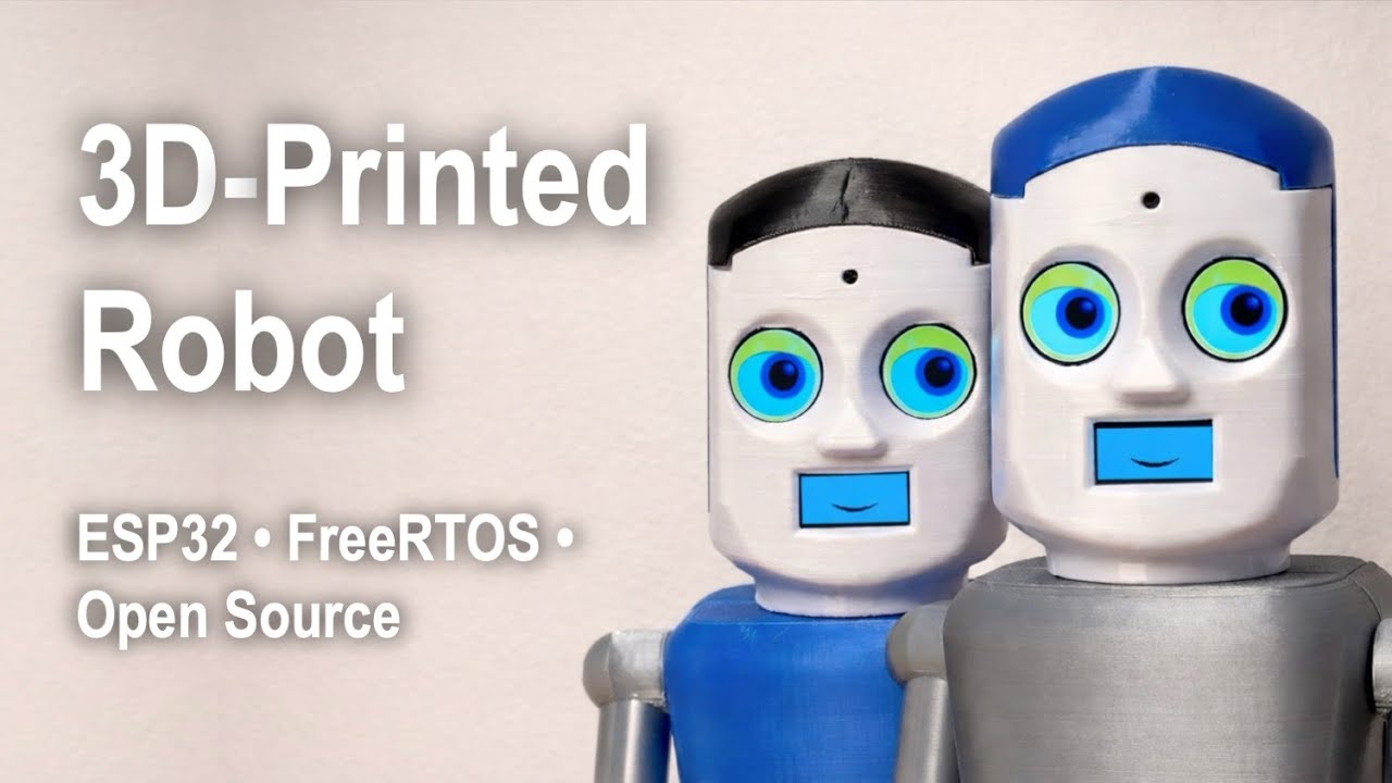
Why this video: This demonstration shows how FreeRTOS manages concurrent tasks on the ESP32. You will see how to run sensor reading, web server updates, and real-time gait calculations on different processor cores without interrupting leg movements.
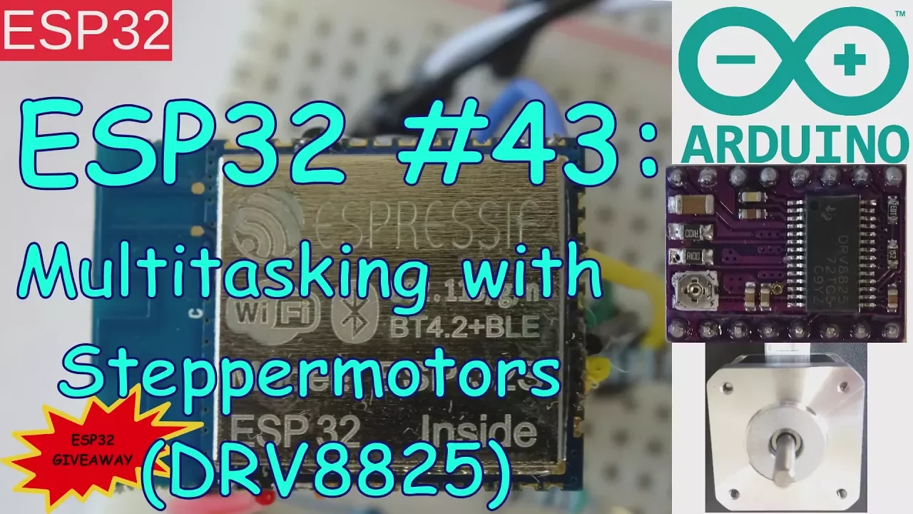
Why this video:
This tutorial walks you through setting up multitasking with FreeRTOS in the Arduino IDE. You will learn to use xTaskCreatePinnedToCore to pin critical kinematic calculations to Core 1, keeping Core 0 free for Wi-Fi and web communications.
Curriculum Note on Coding Gaps: Because there are few pre-made FreeRTOS gait engine tutorials, you will need to write the task loop structure yourself. Build your program with two primary tasks:
GaitEngineTask(pinned to Core 1, running at a steady 50Hz/20ms interval) to calculate coordinate trajectories, run your IK formulas, and write the angles to the PCA9685.NetworkTask(running on Core 0) to handle incoming web connections and control signals.
// Conceptual FreeRTOS Task Architecture void setup() { // Initialize PCA9685 & Wi-Fi xTaskCreatePinnedToCore(GaitEngineTask, "GaitEngine", 4096, NULL, 3, NULL, 1); xTaskCreatePinnedToCore(NetworkTask, "Network", 4096, NULL, 1, NULL, 0); }
Knowledge Checkpoint
- Write a 1D Bézier curve interpolation function in C++ using four control points to define leg lift height.
- Create a Finite State Machine (FSM) in C++ that cycles each leg through
STANCE,LIFT,SWING, andRETRACTstates. - Implement two concurrent tasks in FreeRTOS and use serial prints to verify they are running on Core 0 and Core 1 independently.
- Combine your IK calculations and Bézier trajectory code into your gait engine to run a single, smooth step cycle on one leg.
Module 5: Web-Based Remote Control Interface
In this final module, you will build a remote control interface for your robot. You will configure the ESP32 as a standalone Wi-Fi Access Point, host a lightweight HTML5 web server directly on the board, and implement WebSockets to stream joystick data to your gait engine with minimal delay.
Recommended Videos
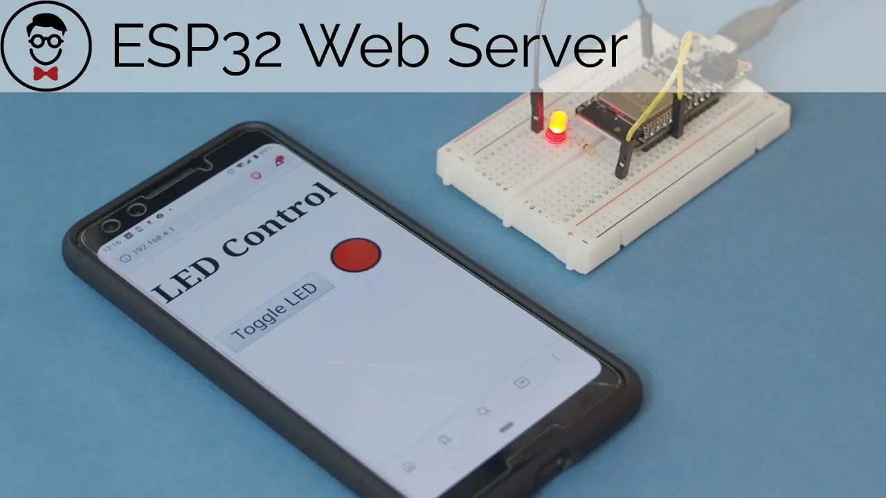
Why this video: This tutorial shows how to set up an ESP32 WebSocket server in the Arduino IDE. WebSockets allow the robot and your control device to send data back and forth instantly over a single persistent connection, making it much faster than standard HTTP requests.

Why this video: This project shows how to build an interactive web page to control motors from a mobile screen. You will learn how to design touch-friendly web buttons and sliders using HTML5 and JavaScript to send control commands back to the ESP32.

Why this video: This walkthrough shows how to build a virtual joystick in JavaScript using the p5.js library. You will learn to map touch coordinates on your screen to direction vectors, allowing you to stream steering inputs ( coordinates) over a network connection.
Curriculum Note on Joystick Gaps: Since many joystick tutorials rely on heavy game engines, focus on building a simple, pure JavaScript touch interface. Use an open-source library like nipplejs or draw a custom joystick on an HTML5 canvas. When the user moves the virtual joystick, have JavaScript bundle the coordinates into a small JSON string (e.g.,
{"x": 0.75, "y": -0.2}representing direction and speed) and send it over the WebSocket connection.
Knowledge Checkpoint
- Configure the ESP32 in Access Point (AP) mode to broadcast its own private Wi-Fi SSID network.
- Build a single HTML/JS webpage featuring a virtual joystick that reads touch drag coordinates () scaled between
-1.0and1.0. - Implement the
ESPAsyncWebServerandAsyncWebSocketlibraries in your C++ code to receive text packets. - Parse incoming JSON joystick packets on the ESP32 and map the directional values to your gait engine's target step vectors.
Course Map
Key People Index
- James Bruton (YouTube Creator & Robotics Engineer): Well-known in the maker community for his open-source robotics research. His openDog series provides valuable practical insights into building DIY legged robots and implementing kinematic control.
- Shawn Hymel (Embedded Systems Engineer & Educator): Former SparkFun engineer whose tutorials clarify complex ESP32 features, such as building asynchronous WebSocket web servers and running tasks in FreeRTOS.
Final Self-Assessment
Perform this final integration test to ensure all hardware and software components of your quadruped are working correctly:
- Hardware Isolation Verification: Confirm the PCA9685 driver and all servos are powered by an external battery, with only the logic connections (SDA, SCL, GND) tied to the ESP32.
- I2C Scanner Test: Run an I2C scan script to confirm the ESP32 successfully detects the PCA9685 at its default address (
0x40). - Chassis Homing Check: Verify all legs align perfectly perpendicular or parallel to the chassis when your calibration script sets the servo offsets to their neutral positions.
- Kinematic Output Accuracy: Input target foot coordinates (such as ) and confirm the calculated joint angles mathematically match your Law of Cosines equations.
- Dual-Core Execution Stability: Verify that kinematic trajectories and WebSocket networking run simultaneously on separate ESP32 cores without dropping connection packets or causing leg movements to stutter.
- Bézier Path Verification: Confirm the physical foot paths follow smooth curves during step cycles, lifting cleanly off the ground and landing softly without slapping.
- AP & Webpage Delivery: Connect your phone or laptop to the ESP32's Wi-Fi Access Point, open the control page, and verify the virtual joystick interface loads correctly.
- Low-Latency Loop Test: Ensure that moving the web joystick instantly triggers corresponding walking movements on the robot without any visible lag or delay.