Microbial Fuel Cells: Design, Bacteria & Power
Learning Goal: Design, build, and optimize a Microbial Fuel Cell (MFC) system for organic wastewater treatment. By the end of this curriculum, you will be able to select optimal anode/cathode materials, perform anaerobic exoelectrogenic inoculations using wastewater sludge, calculate Coulombic efficiency and chemical oxygen demand (COD) removal, and execute electrochemical testing—specifically plotting polarization curves and optimizing internal resistance for maximum power density.
- Prerequisites: Basic chemistry (redox reactions), introductory microbiology, and basic electrical circuits (Ohm's Law, resistance).
- Estimated Study Time: 16 Hours
Module 1: Foundations of Bioelectrochemistry and MFCs
This module covers the basic bioelectrochemical principles that govern living batteries. You will learn how electrogenic microbes oxidize organic matter and directly transfer metabolic electrons to an anode, transforming chemical energy from organic waste into electrical current.
Recommended Videos

Why this video: Taught by Prof. Mainak Das of IIT Kanpur, this lecture establishes the rigorous interface between biological systems and electrochemical reactions. It explains how charge transfer processes occur across biological membranes, which is essential for understanding microbial electron transfer.
Knowledge Checkpoint:
- Understand the biological and physical interfaces where bioelectrochemistry operates.
- Identify how cellular metabolic pathways convert chemical energy into electrical potential.
- Define the fundamental difference between standard chemical redox reactions and bio-catalyzed electrochemical reactions.
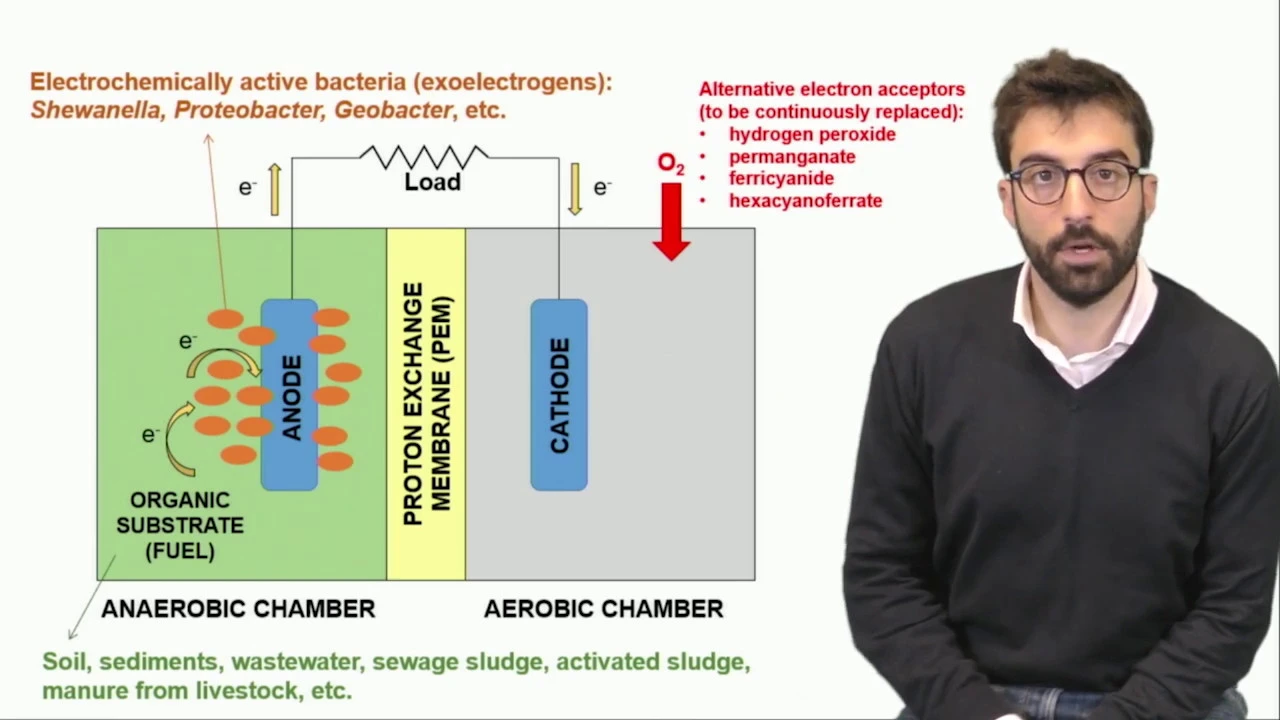
Why this video: This video provides a structured explanation of MFC principles, detailing how organic matter is oxidized in the anaerobic anode chamber and how electrons migrate through an external load to the oxygen-reducing cathode.
Knowledge Checkpoint:
- Diagram the flow of electrons and protons () in a standard MFC.
- Identify why the anode chamber must remain strictly anaerobic to prevent electron losses to oxygen.
- Explain the cathodic oxygen reduction reaction (ORR) and its role in completing the circuit.
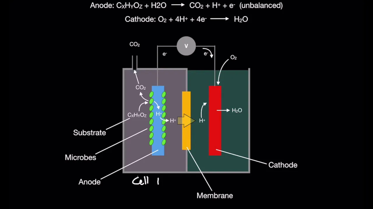
Why this video: This video highlights how MFCs differ from traditional combustion-based biomass energy. It explains how anaerobic electrogens bypass conventional cellular respiration, offering a clear introduction to the physical setup of these bio-batteries.
Knowledge Checkpoint:
- Describe the thermodynamic differences between direct biomass combustion and microbial electrogenesis.
- Identify the main physical boundaries of an MFC (anode, cathode, load, membrane).
Module 2: MFC Architecture and Electrode Selection
This module focuses on the physical design and construction of single vs. dual-chamber MFCs. You will learn about the role of Proton Exchange Membranes (PEM) and structural components like salt bridges, alongside the criteria for selecting high-performance anode and cathode materials.
Recommended Videos

Why this video: This video directly addresses a common design choice by comparing single-chamber and dual-chamber MFC designs. It highlights how separation of the anode and cathode chambers influences waste treatment and power generation.
Knowledge Checkpoint:
- Contrast single-chamber and dual-chamber MFCs in terms of cost, design simplicity, and internal resistance.
- Explain how oxygen intrusion into the anode chamber affects Coulombic efficiency.

Why this video: This video walks through the essential components of a dual-chamber system, focusing on the role of the Proton Exchange Membrane (PEM) in facilitating ion transfer while preventing substrate crossover.
Knowledge Checkpoint:
- Describe the function of a PEM (such as Nafion) in an MFC system.
- Explain how proton transfer rates across the membrane influence the overall pH balance and cell voltage.

Why this video: This video demonstrates the practical side of MFC construction, showing how to prepare high-surface-area electrodes by coating stainless steel mesh with carbon powder and epoxy to encourage bacterial colonization.
Knowledge Checkpoint:
- Explain why high-surface-area materials (e.g., carbon mesh, carbon brushes) make effective anodes.
- Describe how to prepare a low-cost composite electrode.
- List two common non-corrosive metals suitable for current collectors in an MFC.

Why this video: If commercial PEMs (like Nafion) are unavailable due to budget constraints, agar-based salt bridges serve as a functional alternative. This video demonstrates step-by-step how to synthesize and cast a salt bridge.
Knowledge Checkpoint:
- Formulate a standard agar salt bridge using appropriate ratios of agar, water, and salt (e.g., ).
- Explain how the ionic concentration of the salt bridge limits or enhances proton transport.
Structural Design Summary: Single vs. Dual Chamber
Single Chamber MFC Dual Chamber MFC ┌────────────────────────┐ ┌─────────────────┬─────────────────┐ │ [ Wastewater ] │ │ [Anode Chamber]│ [Cathode Chamber] │ Anode (Biofilm) │ │ Anode │ Cathode │ │ (Anaerobic) │ │ (Anaerobic) │ (Aerobic) │ │ │ │ │ │ │ PEM ──► Air Cathode │ │ ◄─── PEM/ ───► │ │ (Exposed) │ │ Salt Bridge │ └────────────────────────┘ └─────────────────┴─────────────────┘
Module 3: Electrogenic Bacteria and MFC Inoculation
This module covers the biology of electrogenic microorganisms (exoelectrogens), their mechanisms of extracellular electron transfer (EET), and practical techniques for inoculating MFCs using mixed cultures from anaerobic municipal or river sludge.
Recommended Videos

Why this video: This video reviews the biology of exoelectrogens (Proteobacteria, Firmicutes, Acidobacteria) and explains the three core extracellular electron transfer (EET) pathways: direct contact via outer-membrane cytochromes, conductive nanowires, and soluble electron shuttles.
Knowledge Checkpoint:
- Define Extracellular Electron Transfer (EET).
- Contrast direct electron transfer (using cytochromes and pili/nanowires) with mediated electron transfer (using endogenous or exogenous electron shuttles).
- List key genera associated with high power densities in MFCs (e.g., Geobacter, Shewanella).

Why this video: This video focuses on Geobacter, a genus of electrogenic bacteria, detailing how they construct conductive protein nanowires to transfer metabolic electrons directly to insoluble metal oxides or anode electrodes.
Knowledge Checkpoint:
- Explain how Geobacter uses protein nanowires (pili) to respire on solid-state acceptors.
- Explain why Geobacter outcompetes many other microbes under strict anaerobic, anode-associated conditions.

Why this video: This video provides a practical guide on using anaerobic river or pond sludge to inoculate an MFC, showing how to handle raw waste material to jumpstart biofilm formation on the anode.
Knowledge Checkpoint:
- Describe the process of harvesting and handling anaerobic benthic mud/sludge for inoculation.
- Explain why adding a supplemental carbon source (e.g., acetate or sugar water) helps establish the biofilm during the initial startup phase.
Module 4: Wastewater Treatment and COD Removal
This module links energy recovery to environmental cleanup. You will study how MFCs degrade organic pollutants, learn to measure Chemical Oxygen Demand (COD) reduction using standard assays, and calculate the system's Coulombic Efficiency.
Recommended Videos

Why this video: This video reviews the chemical principles behind Chemical Oxygen Demand (COD). Understanding COD as an empirical measure of chemically oxidizable organic matter is key to evaluating the wastewater treatment capacity of an MFC.
Knowledge Checkpoint:
- Define Chemical Oxygen Demand (COD) and explain its units ().
- Contrast COD with Biochemical Oxygen Demand (BOD).
- Write down the role of potassium dichromate () in the standard COD assay.
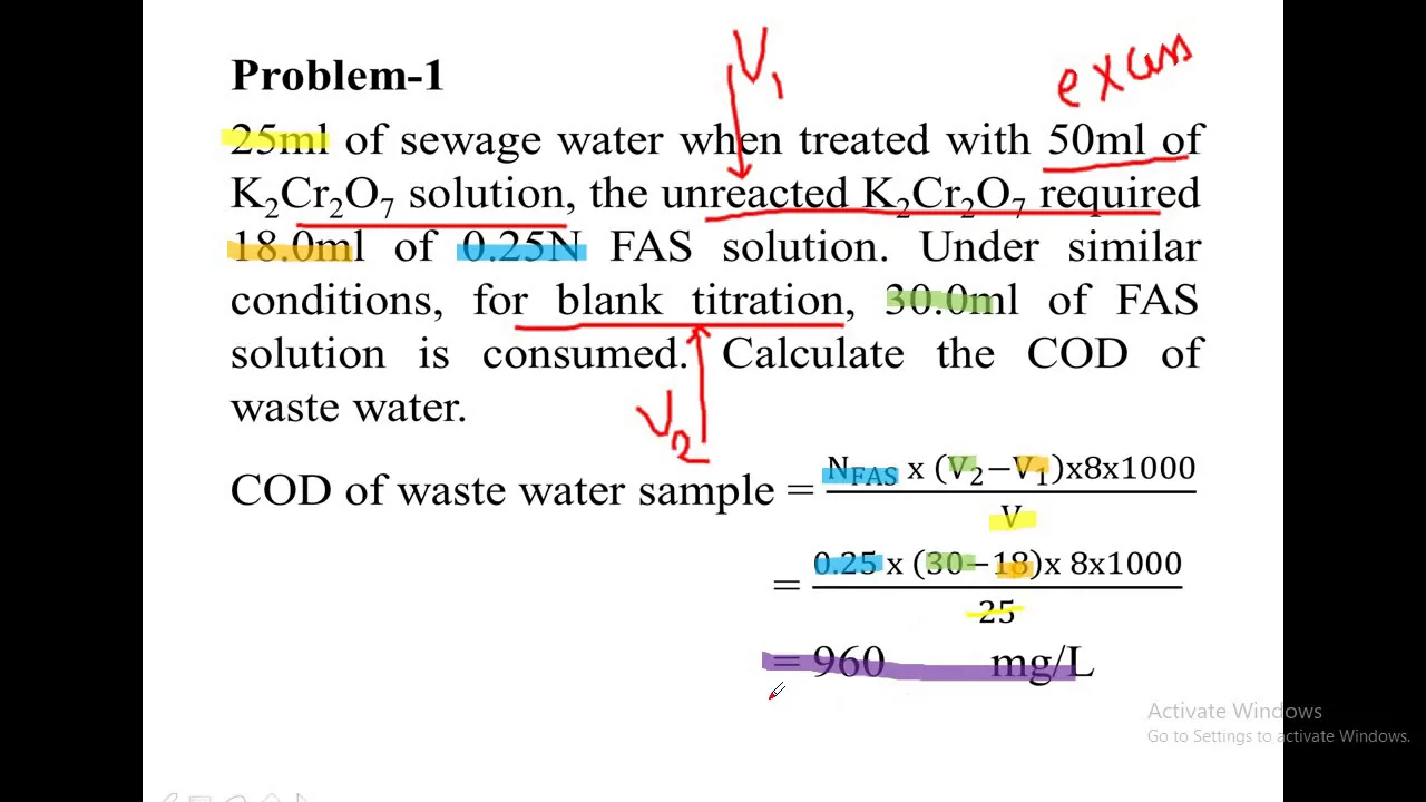
Why this video: This video walks through standard calculations for COD values using titration data, typically involving Ferrous Ammonium Sulfate (FAS). These calculations are necessary for quantifying COD removal across the MFC.
Knowledge Checkpoint:
- Calculate wastewater COD based on titration values using the formula:
- Compute the percentage of COD removal efficiency over a specified operation period:

Why this video: This video introduces the core electrochemical concept of Coulombic Efficiency (CE)—the ratio of charge recovered during discharge to charge stored or added.
Knowledge Checkpoint:
- Understand the concept of round-trip coulombic efficiency in charge storage systems.
- Relate charge recovery directly to electron transfer pathways.
Supplemental Lecture: Calculating MFC Coulombic Efficiency ()
Because the video pool lacks a direct video on calculating Coulombic Efficiency specifically for MFCs, study the formula below to complete your knowledge:
Coulombic Efficiency () in an MFC is the ratio of recovered coulombs (integrating the current over time) to the theoretical maximum coulombs available from the fully oxidized organic matter (measured as COD reduction):
Where:
- (molecular weight of ).
- = Current generated by the cell over time ().
- (Faraday's Constant).
- (electrons exchanged per mole of oxygen).
- = Liquid volume of the anode chamber ().
- = Change in COD concentration () over the time interval.
Example Calculation: If an MFC runs for 24 hours (), generates a steady current of (), has an anode liquid volume of , and the COD drops from to ():
- Recovered Charge ():
- Theoretical Max Charge ():
- Coulombic Efficiency ():
Module 5: Power Density Optimization and Electrochemical Testing
In this advanced module, you will learn how to measure the performance of your MFC system. You will study polarization and power curves to identify internal resistance, optimize external loads, and understand strategies for scaling up systems.
Recommended Videos
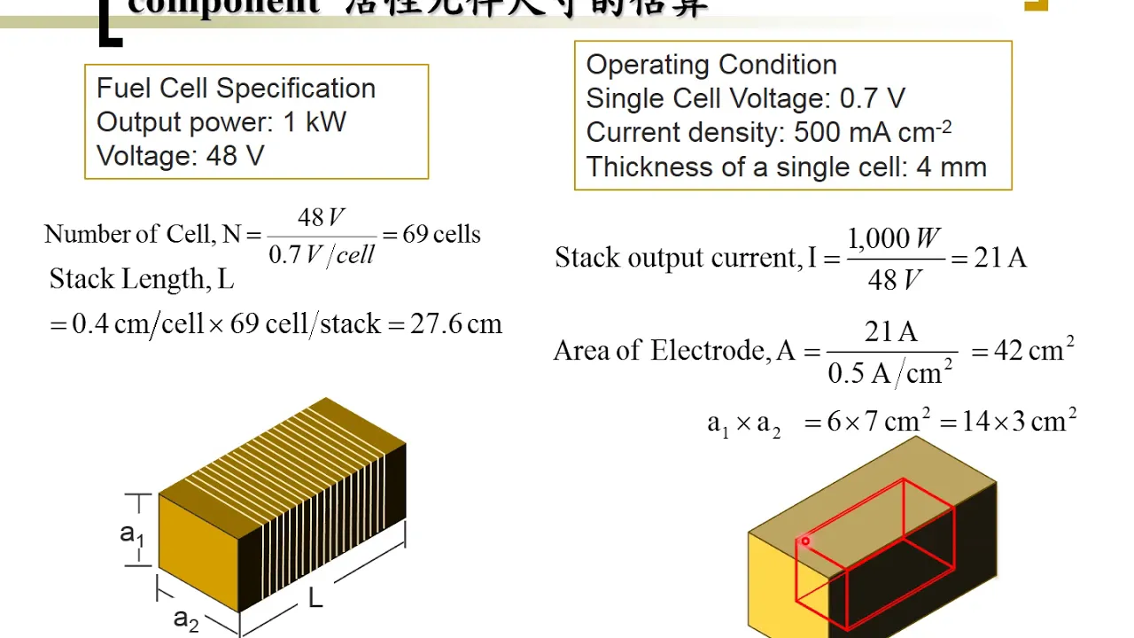
Why this video: This video introduces polarization curves, showing how cell voltage drops as current density increases. It explains how to plot and interpret voltage vs. current density curves to evaluate power density.
Knowledge Checkpoint:
- Define current density () and power density ( or ) in the context of active anode surface area/volume.
- Explain why cell voltage drops as current drawn from the system increases.
[
| Channel | Duration | Views |
|---|---|---|
| @hsueh_kan-lin | 04:10 | 4,911 |
Why this video: This video details the three core regions of a fuel cell polarization curve: activation polarization (kinetics at low current), ohmic polarization (internal resistance at intermediate current), and concentration polarization (mass transport limitations at high current).
Knowledge Checkpoint:
- Sketch a typical polarization curve and label the activation, ohmic, and mass transport (concentration) loss regions.
- Identify which physical processes cause losses in each of these three regions.

Why this video: This video teaches the Maximum Power Transfer Theorem, which states that a cell delivers maximum power to an external load when the external load resistance () equals the internal resistance () of the source.
Knowledge Checkpoint:
- State the Maximum Power Transfer Theorem mathematically.
- Apply this theorem to optimize MFC performance by selecting an external resistor that matches the cell's internal resistance.
Supplemental Guide: Testing and Plotting an MFC Polarization Curve
Because the video pool lacks a direct, step-by-step practical guide on plotting an MFC-specific polarization curve, use the following protocol:
Polarization & Power Curve Protocol
-
Preparation: Allow the MFC to reach its steady-state Open Circuit Voltage (OCV) under a no-load condition (voltmeter connected, no circuit completed). Record this voltage as .
-
Variable Load Testing: Connect a decade resistor box (or switch individual resistors) in series across the MFC.
-
Measurement: Start with a high resistance (e.g., ) and decrease step-by-step (e.g., ).
- For each resistor, wait for the voltage output to stabilize (usually 10–20 minutes) and record the stable voltage () and the resistance ().
-
Calculations:
- Current (): Calculate using Ohm's Law:
- Power (): Calculate power:
- Normalization: Divide current and power by the active anode surface area () to find Current Density () and Power Density ():
-
Plotting: Plot Voltage () vs. Current Density () as the primary polarization curve. On the same x-axis, plot Power Density () vs. Current Density (). The peak of this second curve represents the maximum power density (). The slope of the linear (middle) region of the polarization curve represents the internal resistance () of the MFC.
Polarization Curve (V vs J) and Power Curve (P vs J)
Voltage (V) Power Density (P)
│ │
OCV│* │
│ \ │
│ \ Ohmic Loss Region │ * Peak Power
│ __ (Slope = Internal Resistance) │ /
│ \ │ /
│ \ │ /
0└──────────────────────────► Current Density (J)└───────────► (J)
Course Map
Key People Index
- Dr. Derek Lovley: Pioneered research into Geobacter metallireducens and the discovery of microbial nanowires. His foundational work proved that bacteria can transfer electrons directly to metals and conductive anodes.
- Dr. Bruce Logan: A leading researcher in Microbial Fuel Cell technologies and wastewater-to-energy conversion systems at Penn State University. He developed several modern anode geometries (e.g., carbon brushes) and continuous-flow MFC designs.
- Prof. Mainak Das: Bioelectrochemist and professor at IIT Kanpur; specialist in the engineering interface between biological membranes, electronic materials, and bio-catalyzed charge transfer.
- Dr. Yi Cui: Materials scientist at Stanford University who advanced nanostructured electrodes, showcasing how materials science can improve microbial adhesion and reduce internal charge-transfer resistance.
Final Self-Assessment
Before concluding, confirm your understanding of the core concepts in this curriculum by completing this comprehensive self-assessment checklist:
- Can you write down the half-cell oxidation reaction of a simple organic substrate (e.g., acetate ) occurring at the bio-anode?
- Can you explain why oxygen intrusion into the anode chamber decreases Coulombic Efficiency ()?
- Do you know how to choose an appropriate anode material based on surface roughness, biocompatibility, and electrical conductivity?
- Can you state the difference between direct electron transfer via outer-membrane cytochromes and mediated transfer via chemical redox mediators?
- Are you able to prepare a functional, low-cost salt bridge using agar-agar and sodium chloride ()?
- Do you know how to dilute and inoculate an MFC with raw anaerobic digester sludge safely under laboratory conditions?
- Can you calculate the COD of a wastewater sample using FAS titration values?
- Can you calculate the overall Coulombic Efficiency () of an MFC given the volume, operating time, mean current, and COD reduction?
- Can you identify the three distinct loss regions (activation, ohmic, concentration) on an experimental MFC polarization curve?
- Can you apply the Maximum Power Transfer Theorem to match an external circuit load to your MFC's internal resistance?