3-Axis Robotic Arm: Raspberry Pi & Kinematics
Learning Goal: Design, assemble, and program a 3-axis robotic arm using servo motors and a Raspberry Pi, implementing inverse kinematics for precise pick-and-place operations.
- Estimated Total Study Time: 24 hours
- Prerequisites: Basic knowledge of Python programming, high-school-level algebra, and trigonometry (sine, cosine, tangent).
Module 1: Raspberry Pi Foundations & GPIO Basics
This module establishes the foundational hardware and software skills required to operate a Raspberry Pi. You will learn the mechanical layout of the Pi, its electrical specifications, and how to control digital outputs (such as blinking an LED) using the Python programming language and General Purpose Input/Output (GPIO) pins. This setup forms the "brain" of our robotic arm.
Recommended Videos
Why this video: This video provides a thorough hardware and history overview of the Raspberry Pi. It is the perfect entry point for absolute beginners to understand what the board is, how it operates as a full-fledged computer, and how to prepare it for physical computing.
- Knowledge Checkpoint:
- Understand the power requirements of the Raspberry Pi.
- Identify where the MicroSD card slot is located and how to flash an OS image.
- Locate the 40-pin GPIO header on the board.
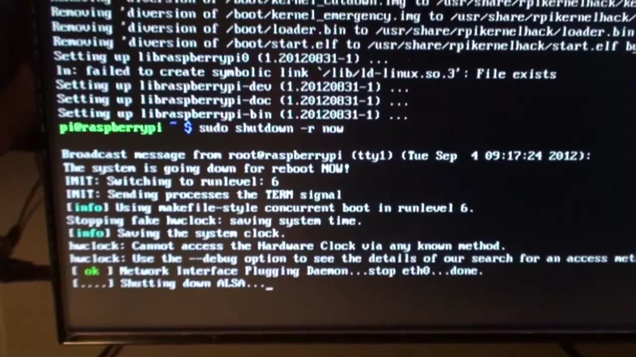
Why this video: This comprehensive walkthrough takes you deeper into the pinout configuration of the Raspberry Pi. It explains the distinction between physical pin numbering and BCM (Broadcom) GPIO numbering schemes, which is vital for writing bug-free Python hardware scripts.
- Knowledge Checkpoint:
- Distinguish between physical pin numbering (BOARD) and Broadcom numbering (BCM).
- Identify safe voltage tolerance levels for GPIO input/output (3.3V vs 5V warning).
- Locate Ground (GND), 5V power, and 3.3V power rails on the header.

Why this video: This is a highly practical hands-on guide to assembling your first physical circuit on a breadboard and controlling it using Python. It covers importing the RPi.GPIO module, setting pin directions, and driving an LED output.
- Knowledge Checkpoint:
- Correctly wire an LED to a Raspberry Pi GPIO pin using a current-limiting resistor (e.g., 330Ω) on a breadboard.
- Set a GPIO pin mode as an output using Python.
- Write a basic Python script that switches a GPIO pin
HIGHandLOWwith time delays.
Module 2: Actuators & PWM Servo Control
Robotic joints require precise position control. This module covers how servo motors operate internally using feedback loops and how they are controlled using Pulse Width Modulation (PWM). You will learn to generate precise PWM signals using the Raspberry Pi and explore the critical requirement of external power supplies when controlling multiple servos to prevent damaging your Pi.
Recommended Videos
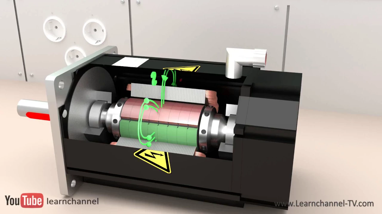
Why this video: This highly visual animation breaks down what happens inside the casing of a servo motor. It explains how the closed-loop system uses a DC motor, gear reduction, a potentiometer for position feedback, and an integrated control board to maintain its target angle.
- Knowledge Checkpoint:
- Understand the role of the internal potentiometer in a closed-loop servo system.
- Explain how a gear train translates high-speed DC motor rotation into high-torque angular movement.
- Define the purpose of the three-wire interface (Power, Ground, and Signal).

Why this video: This deep-dive programming tutorial demonstrates how to configure PWM outputs directly from Python. It explains the relationship between PWM frequencies (specifically 50 Hz), duty cycle percentages, and corresponding physical angles (0° to 180°).
- Knowledge Checkpoint:
- Calculate the duty cycle required for specific angles (e.g., 1.5ms pulse width for a 90° center position at 50 Hz).
- Create and start a PWM object in Python using
GPIO.PWM(). - Implement smooth angular changes by incrementally updating the duty cycle in a loop.
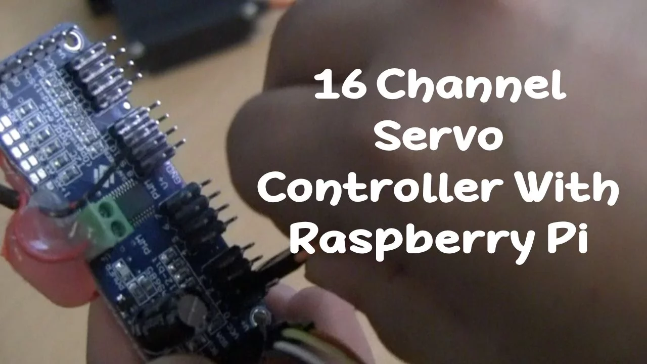
Why this video: This tutorial directly addresses a vital curriculum gap: driving multiple servos safely without overloading the Raspberry Pi. It guides you through using an I2C-based PCA9685 16-channel PWM driver board, offloading the timing generation from the Pi's CPU and providing a dedicated terminal block to attach an external power supply safely.
- Knowledge Checkpoint:
- Map the physical wiring connections between the Raspberry Pi (SDA, SCL, 3.3V, GND) and the PCA9685 board.
- Enable the I2C interface on your Raspberry Pi using the system configuration utility.
- Explain why the PCA9685's opt-isolated external V+ terminal block is necessary to safely power multiple heavy-current SG90 or MG996R servos.
Module 3: Mechanical Design & Arm Assembly
In this module, you will transition from electronics to mechanics. You will learn about degrees of freedom (DoF), structural links, and revolute joints. Crucially, you will explore how torque requirements dictate servo motor selection, and see how a typical 3-axis desktop arm is physically assembled.
Recommended Videos
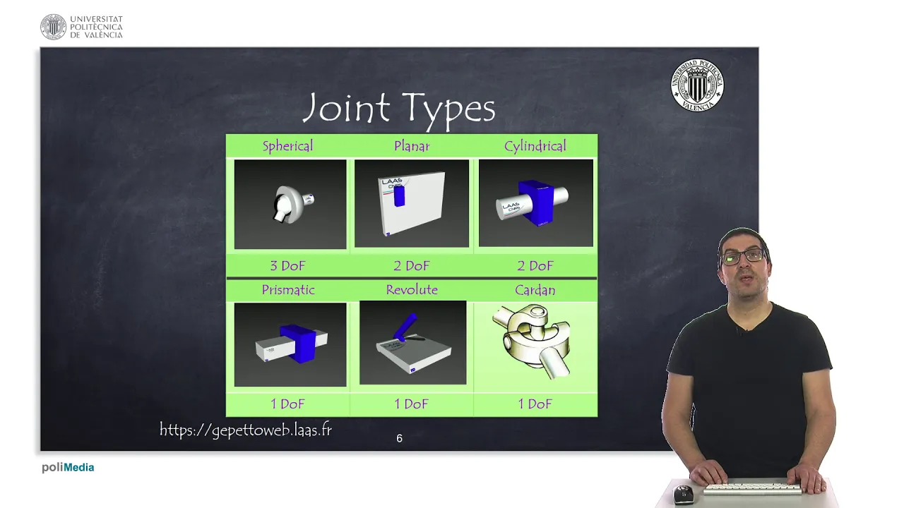
Why this video: This academic yet clear video introduces the foundational vocabulary of mechanical linkages. You will learn how joints constrain movement and how to calculate the degrees of freedom in a physical multi-link system.
- Knowledge Checkpoint:
- Define the difference between a "link" (rigid body) and a "joint" (degree of freedom constraint).
- Differentiate between revolute (rotational) and prismatic (linear) joints.
- Map the links and joints of your physical 3-axis robotic arm.
Why this video: This concise engineering snippet addresses the curriculum gap on calculating servo torque requirements. It demonstrates how structural length (lever arm) and load weight influence the rotational torque required at the joint hinge, measured in kilogram-centimeters (kg·cm) or Newton-meters (N·m).
- Knowledge Checkpoint:
- Calculate the torque required for a joint holding a physical arm link horizontally: .
- Apply safety factor considerations to choose a servo with stall torque exceeding your worst-case calculations.

Why this video: This video focuses on structural assembly and physical design challenges. It details working with standard mounting brackets, routing cables cleanly, and mitigating mechanical friction in 3D-printed plastic components.
- Knowledge Checkpoint:
- Align physical servo gears to their center range of motion before screwing down mechanical links.
- Understand methods for reducing mechanical play (backlash) and friction at the hinge joints.
- Learn how standard hardware (such as screws and spacers) secure 3D-printed arm links.
Module 4: Coordinate Systems & Forward Kinematics
Once your arm is assembled, you need to map joint rotations to the physical world. This module focuses on coordinate systems (2D and 3D space) and the mathematics of Forward Kinematics. Instead of complex academic Denavit-Hartenberg (D-H) parameter matrices, we focus on a direct, highly intuitive Trigonometric Approach suited for standard 3-axis arms.
Recommended Videos

Why this video: This academic lecture introduces coordinate systems and frames of reference. It explains how local coordinate systems at each individual joint are sequentially transformed into a global "world coordinate system" relative to the robot's base.
- Knowledge Checkpoint:
- Explain how the origin of a robotic arm is defined at its physical base center.
- Understand translational and rotational transformations in 3D space.
- Differentiate local joint coordinates from global Cartesian coordinates ().

Why this video: This tutorial cuts straight to the core math. It avoids matrix math and explains how to solve the position of an arm's end-effector using basic trigonometric functions (sine and cosine).
- Knowledge Checkpoint:
- Write trigonometric equations calculating the horizontal position () and height () of a 2-segment arm link using joint angles and .
- Draw coordinate triangles representing individual arm link projections.
- Use Python's math library (
math.sinandmath.cos) to output coordinate variables from angular values.
Module 5: Inverse Kinematics (IK) Mathematics
While forward kinematics calculates positions from angles, Inverse Kinematics (IK) does the opposite: it takes a desired target Cartesian coordinate () and calculates the exact joint angles required to reach it. This is the heart of precise robot control. We will derive this using a geometric/trigonometric approach utilizing the Law of Cosines.
Recommended Videos

Why this video: This video is an incredibly practical, concise mathematical breakdown. It demonstrates how to resolve a 3-axis arm's inverse kinematics using just five lines of geometry and trigonometry, dividing the problem into base rotation () and two planar angles (, ).
- Knowledge Checkpoint:
- Derive the base horizontal rotation angle () using the target coordinates: .
- Solve the geometric projection of the virtual triangle connecting the shoulder joint to the target wrist.
- Identify physical boundary limits where target coordinate positions are mathematically "unreachable" (out of bounds).

Why this video: This academic lecture expands on the geometric derivation. It systematically steps through the algebraic equations, utilizing the Law of Cosines to solve the "elbow-up" and "elbow-down" configurations of the arm's mechanical links.
- Knowledge Checkpoint:
- Write the equation for the Law of Cosines: .
- Rearrange terms to isolate and solve the joint angles as inverse cosine () functions.
- Understand why there are typically two distinct physical solutions ("elbow-up" vs "elbow-down") for reaching a single 3D point.
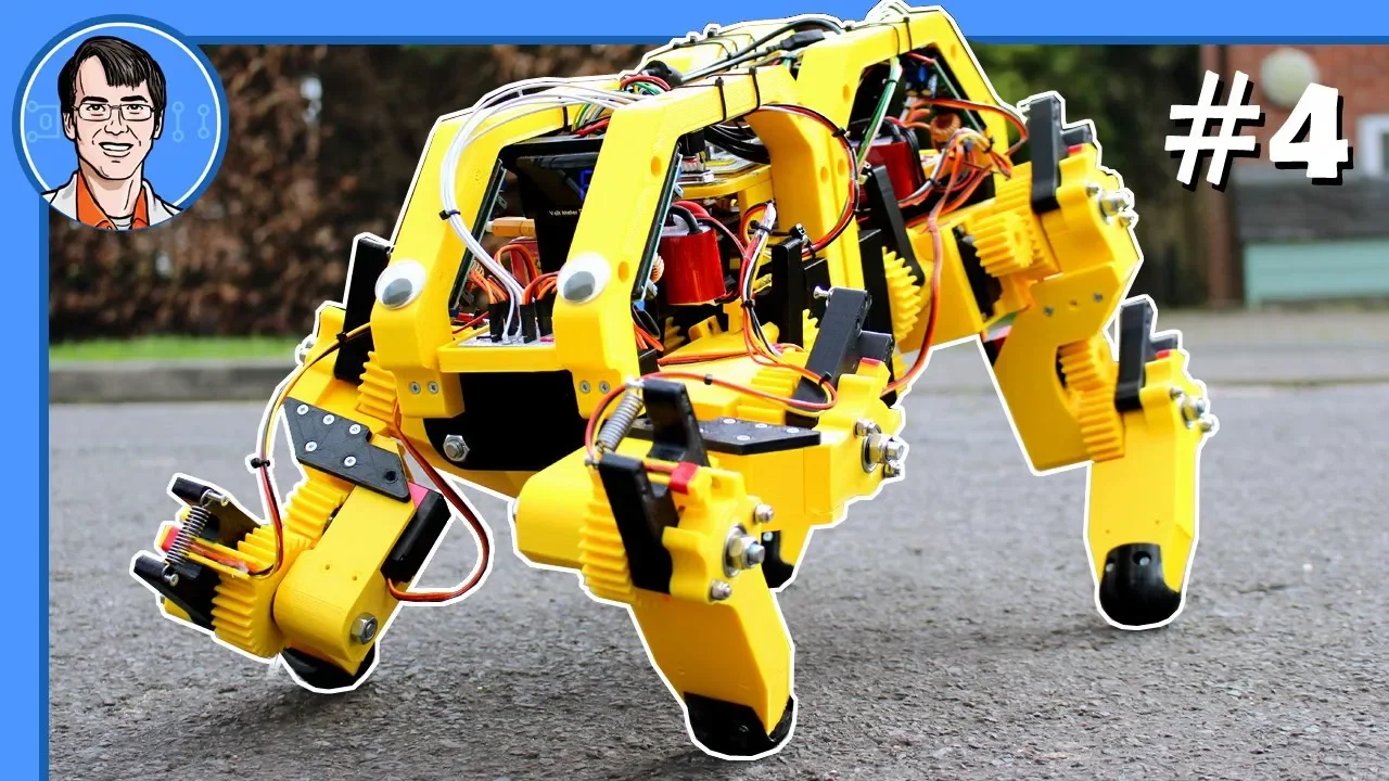
Why this video: This video bridges raw whiteboard theory with practical physical code. While demonstrating a robotic leg, the underlying kinematics are identical to a 3-axis arm link, walking you through translating Side-Side-Side (SSS) geometric triangles directly into functional programming code.
- Knowledge Checkpoint:
- Map the physical link lengths (, ) as known constant inputs in your IK math model.
- Calculate the distance from base origin to target point: .
- Implement mathematical checks to prevent sending complex imaginary outputs (caused by passing values or to standard ) to the servos.
Module 6: Programming & Pick-and-Place Automation
This final module integrates your hardware (Raspberry Pi & PCA9685) with your math model (IK equations) to execute real-world automated tasks. You will orchestrate sequential coordinates to execute a complete "Pick-and-Place" movement cycle: hovering, descending, closing the gripper, rising, traversing, and releasing.
Curriculum Note on Video Coverage: Videos in this area are heavily split between complex industrial workspace simulators (like ABB RobotStudio) or basic Arduino playback hacks (where angles are manually "recorded" instead of calculated dynamically via code).
To bridge this gap, you will watch the architectural workflow concepts in the videos below, then implement your own end-to-end Python automation script using the instruction steps mapped out in our Final Projects & Code Structure section.
Recommended Videos

Why this video: This video demonstrates a complete industrial pick-and-place operation sequence. It outlines how multi-axis coordinate frames transition from a baseline homed coordinate, to a pick position, and finally to a drop-off zone.
- Knowledge Checkpoint:
- Explain why returning to a consistent "Home" reference coordinate is necessary.
- Identify safety clearance "hover" height coordinates above the physical object to avoid collisions during sideways moves.
- Understand the logical sequence of pick, lift, transition, descend, and drop.

Why this video: This simulation video models target work-objects and coordinates. It illustrates how precise paths are plotted through points in 3D space to achieve fluid, collision-free arm trajectories.
- Knowledge Checkpoint:
- Define what a "Work Object" coordinate plane represents relative to the robot's base.
- Distinguish between joint-by-joint movement (non-linear path) and linear Cartesian movement paths.
- Plan physical path interpolation (moving intermediate points) so the robot moves in clean, straight lines.
End-to-End Implementation Blueprint (Bridging the Code Gap)
To build your custom, IK-driven Python application, structure your software using this blueprint:
import math import time from adafruit_servokit import ServoKit # Library for PCA9685 driver
1. Configuration & Constants
Link Lengths (in cm)
L1 = 15.0 # Upper Arm L2 = 12.0 # Forearm
Initialize PCA9685 driver via Adafruit CircuitPython library
kit = ServoKit(channels=16)
2. Geometric Inverse Kinematics Function
def calculate_joint_angles(x, y, z): # Base Angle theta1 = math.degrees(math.atan2(y, x))
# Radius in horizontal plane
r = math.sqrt(x**2 + y**2)
# Distance from shoulder joint to wrist joint
d = math.sqrt(r**2 + z**2)

if d > (L1 + L2):
    raise ValueError("Target coordinate is out of physical reach!")

# Law of Cosines for Elbow Hinge (theta3)
cos_theta3 = (L1**2 + L2**2 - d**2) / (2 * L1 * L2)
theta3_rad = math.acos(clip_value(cos_theta3, -1.0, 1.0))
# Convert and adjust for physical arm reference
theta3 = 180 - math.degrees(theta3_rad)

# Law of Cosines for Shoulder Hinge (theta2)
alpha = math.atan2(z, r)
beta = math.acos(clip_value((L1**2 + d**2 - L2**2) / (2 * L1 * d), -1.0, 1.0))
theta2 = math.degrees(alpha + beta)

return theta1, theta2, theta3
def clip_value(val, min_val, max_val): return max(min(val, max_val), min_val)
3. Execution Pipeline
def move_arm_to_coordinate(x, y, z): try: t1, t2, t3 = calculate_joint_angles(x, y, z) # Write precise output to corresponding servo indexes on PCA9685 kit.servo[0].angle = t1 # Base Rotation kit.servo[1].angle = t2 # Shoulder Pitch kit.servo[2].angle = t3 # Elbow Pitch time.sleep(0.5) # Allow physical movement to settle except ValueError as e: print(f"Movement Error: {e}")
Using this Python framework, write an orchestration loop that coordinates these actions in order:
- Hover Coordinate: (, , )
- Descend Coordinate: (, , )
- Gripper Actuation: Close servo on index 3.
- Ascend Coordinate: (, , )
- Traverse Coordinate: (, , )
- Descend Coordinate: (, , )
- Gripper Actuation: Open servo on index 3.
Course Map
Key People Index
- Paul McWhorter: Electronic systems educator. Known for beginner-friendly, deeply detailed tutorials explaining hardware timers, duty cycles, and real-time physical calibration.
- Nikolaus Correll: Professor and robotics researcher. Focuses on coordinate frames, robot kinesthesiology, and spatial path representations.
- James Bruton: Robotics designer and ex-toy engineer. Widely recognized for translating complex inverse kinematics mathematics into straightforward, functional software code blocks for physical hardware prototyping.
Final Self-Assessment
Complete these self-assessment milestones to verify you have mastered the material and constructed a fully operational robotic arm:
- Hardware Isolation: Your servo motors are powered entirely by an independent external 5V/6V DC power supply capable of providing at least 2 Amps, with common grounds connected to the Raspberry Pi.
- PCA9685 Addressable Control: You can address and rotate individual joints of your robotic arm through terminal commands by transmitting parameters to the PCA9685 driver via the Pi's I2C pins.
- No Slop Assembly: All physical joint horns are structurally secure, and linkages show minimal rotational "backlash" or physical sagging when fully extended.
- Torque Validation: Base and shoulder joints can lift the full physical weight of the extended arm plus target payload without stalling or heating up.
- Coordinate Agreement: Your software's spatial origin matches the physical centerline of your robot's rotation base.
- Trigonometric Verification: You can manually input joint angles, run forward kinematics equations, and measure that the physical gripper's position matches your calculated Cartesian coordinates.
- Boundary Protection: Your Python IK software successfully rejects target coordinates that exceed the physical mechanical limit of the arm links, safely printing errors instead of trying to over-rotate physical servos.
- Symmetric IK Execution: Placing a coordinate target within reach (e.g., ) causes the base, shoulder, and elbow servos to automatically execute calculated rotations to position the gripper exactly at that point.
- Autonomous Operation Cycle: Your robotic arm successfully performs an autonomous pick-and-place cycle: hovering over a designated coordinate, grabbing a lightweight object, lifting it, traversing to a target location, and releasing it without manual intervention.