Building Solar Trackers: Arduino, LDRs & Motors
Learning Goal: Design and build a dual-axis solar tracking system using photoresistors, stepper motors, and an Arduino to optimize solar panel power output.
- Prerequisites: None (Absolute beginner-friendly)
- Estimated Total Study Time: 18 Hours
Module 1: Foundations of Solar Energy & Tracking
Learn the fundamental physics of solar cells, understand the geometry of sunlight angles, and analyze how multi-axis movement profiles maximize photovoltaic output.

Why this video
This animated TED-Ed video serves as the perfect visual primer for understanding how sunlight interacts with silicon cells. It details how photons knock electrons loose to create direct current (DC), providing the theoretical foundation necessary to appreciate why direct solar alignment is critical for energy generation.

Why this video
Presented by MIT OpenCourseWare, this lecture clip introduces the physical mechanics of solar tracking. It cleanly defines single-axis and dual-axis architectures, detailing how they align to track the solar path and why dual-axis systems yield the highest performance by constantly countering seasonal elevation shifts.
Why this video
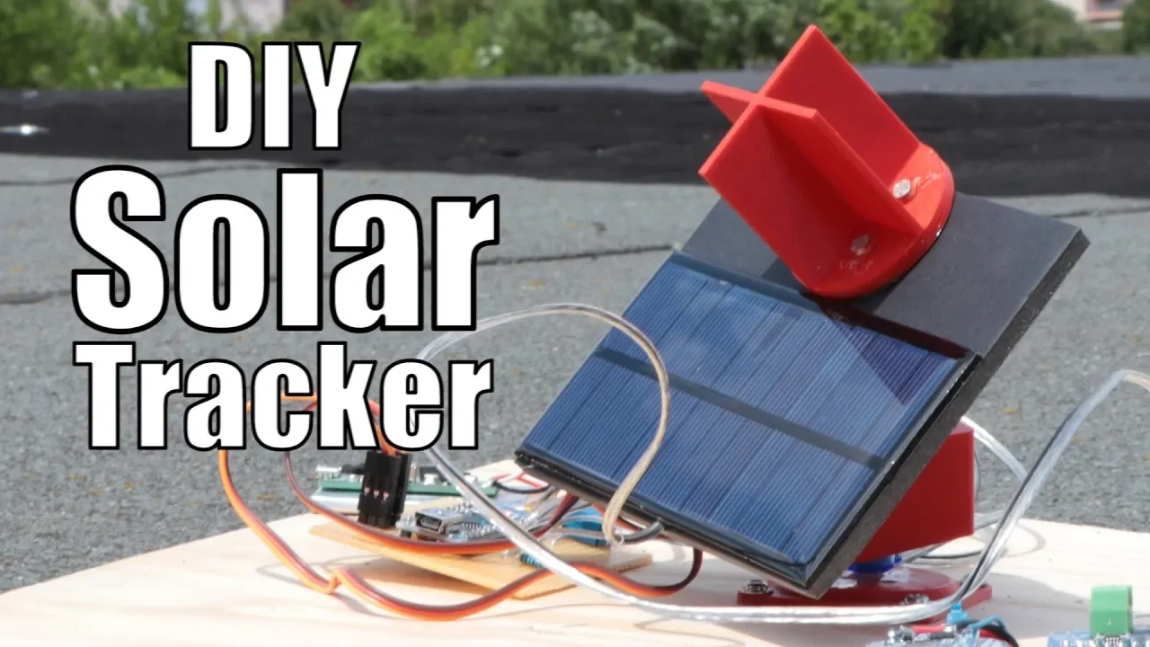
This video provides immediate empirical proof of a solar tracker's benefits. It walks through an experiment demonstrating a ~15% increase in energy harvest compared to fixed panels, establishing real-world justification for your build.
Knowledge Checkpoint
- Describe how photons knock electrons loose in a p-n junction silicon solar cell.
- Explain the core mechanical difference between single-axis and dual-axis trackers.
- Quantify the typical efficiency gains of solar tracking systems over static mounts under real-world conditions.
Module 2: Arduino and Basic Electronics for Beginners
Acquire foundational skills in hardware prototyping. Learn to identify microcontroller components, read circuit schematics, build paths on breadboards, and calculate basic voltage changes.
Why this video
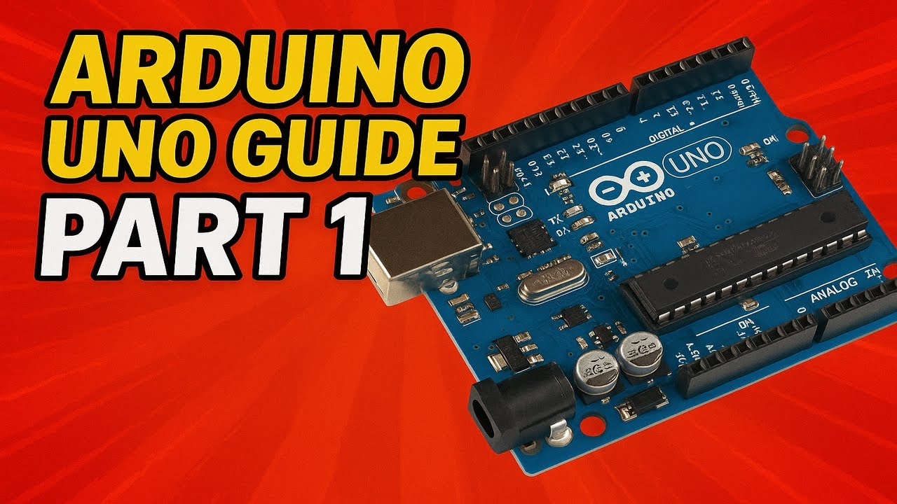
This is a modern, step-by-step introduction to the hardware core of your project: the Arduino Uno. It breaks down the microcontroller's pinout layout, standard specifications, and basic programming environment.
Why this video
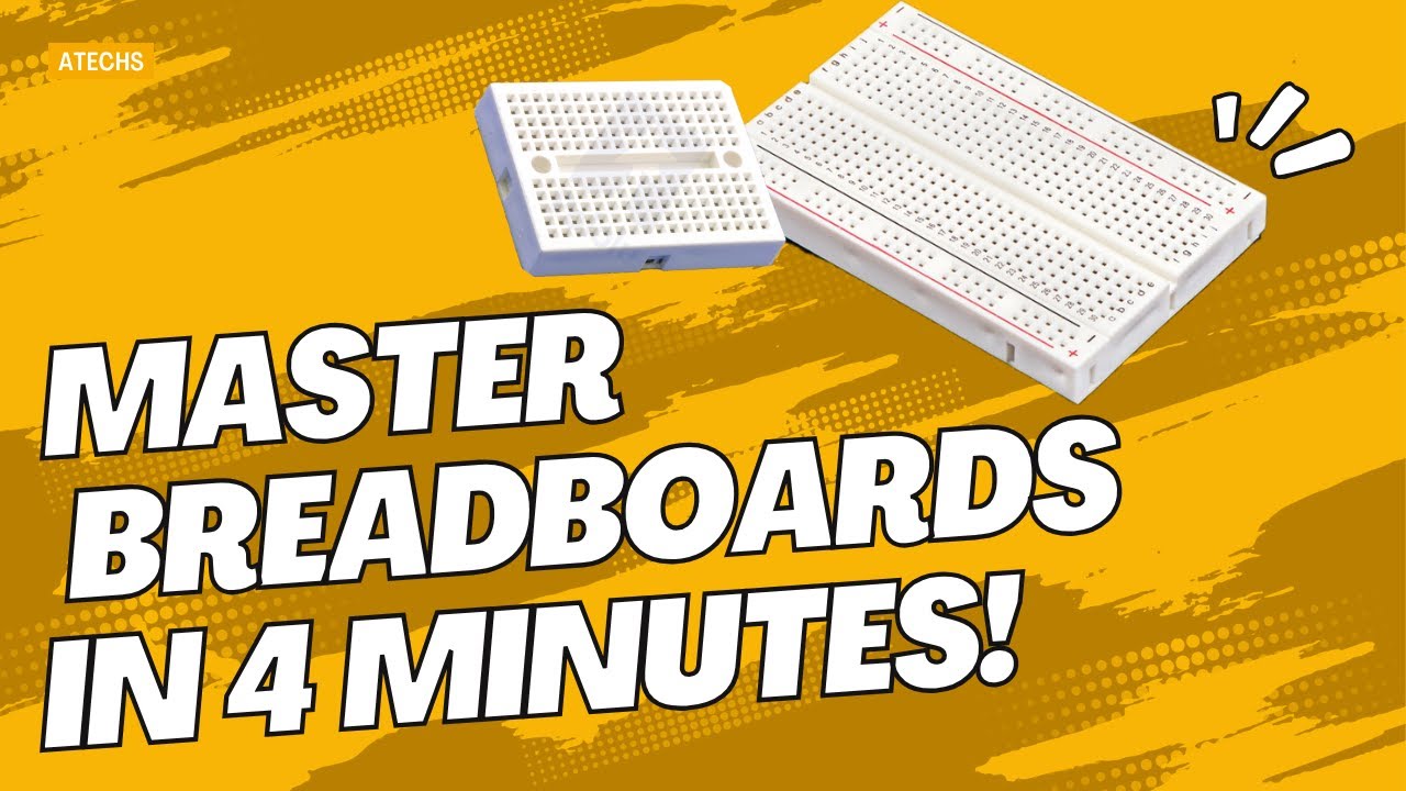
Before wiring any components, you must master the breadboard. This video teaches you how internal metal clips are linked beneath the terminal strips and power rails, preventing short circuits during assembly.

Why this video
Microcontrollers cannot measure pure resistance directly; they can only read changes in voltage. This short guide introduces the voltage divider circuit, the exact electrical technique we will use to read sensor data.
Knowledge Checkpoint
- Locate the 5V, GND, Analog Input (A0-A5), and Digital I/O pins on your Arduino Uno.
- Explain how breadboard columns are connected internally versus how the horizontal power rails run.
- Write the mathematical formula for a basic two-resistor voltage divider.
Module 3: Light Sensing with Photoresistors (LDRs)
Interface Light Dependent Resistors (LDRs) with the Arduino. Learn how LDR resistance shifts under varying illumination, and use a voltage divider to translate this into readable analog data.
Why this video
Paul McWhorter offers an exceptional, comprehensive class on photoresistors. He explains the semiconductor physics of cadmium sulfide LDRs and demonstrates how to build and program a light-sensing circuit.

Why this video
This tutorial focuses specifically on the physical setup of an LDR paired with a 10kΩ static resistor on a breadboard. It illustrates how to route the midpoint junction directly to an Arduino analog pin to sample physical light levels.
Why this video
This video explains how the Arduino’s internal 10-bit Analog-to-Digital Converter (ADC) functions, translating continuous input voltages between 0V and 5V into integer values from 0 to 1023.
Knowledge Checkpoint
- How does an LDR's electrical resistance change when transitioning from complete darkness to bright, direct light?
- Why is a fixed resistor (e.g., 10kΩ) required to build a working sensor circuit with an LDR?
- If an Arduino's analog pin reads a raw ADC value of 512, what is the approximate voltage present at the pin?
Module 4: Actuation with Stepper Motors & Drivers
Configure and control high-precision bipolar stepper motors. Interface a NEMA 17 motor with an A4988 motor driver board to handle movement step pulses and direction signals safely.
Why this video
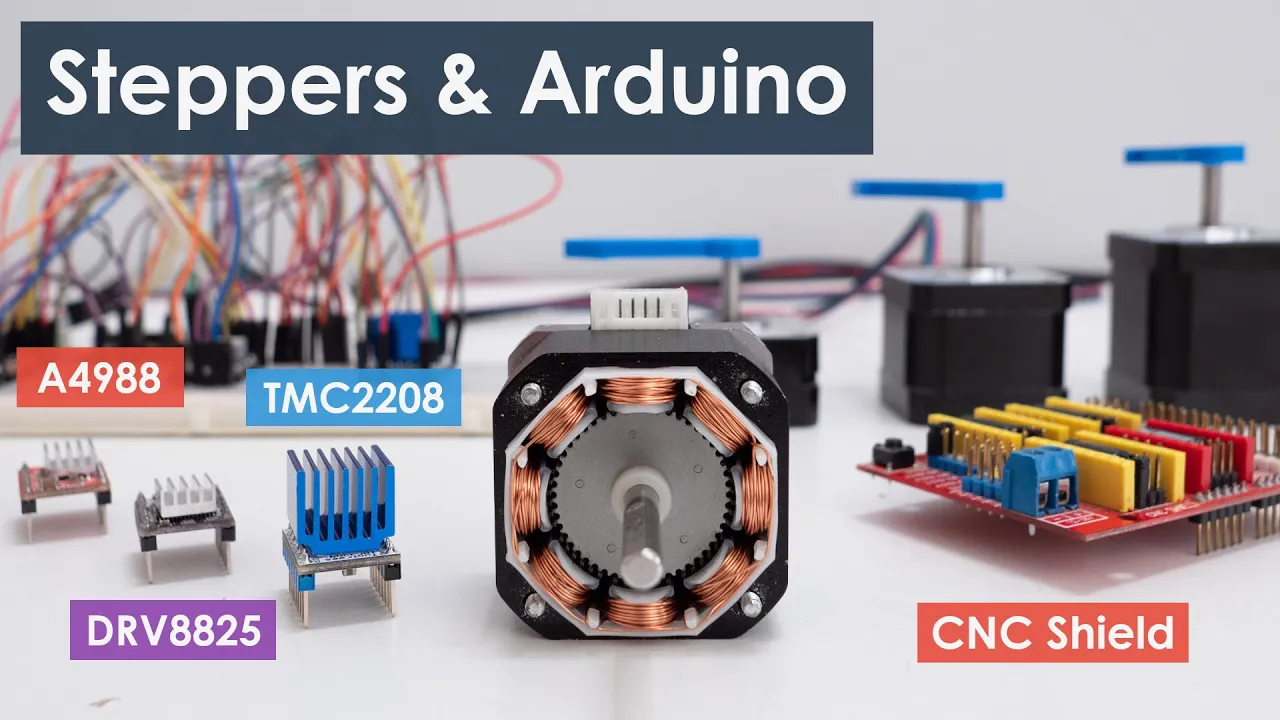
This is a comprehensive guide to understanding stepper motors. It covers internal magnetic stator-rotor operations, basic stepping mechanics, and how dedicated drivers like the A4988 manage current to protect both motor coils and microcontroller pins.
![How to Control NEMA17 Stepper Motor with A4988 Driver and Arduino[with CODE]](https://i.ytimg.com/vi_webp/u0iE0Wrfu2g/maxresdefault.webp)
Why this video
This video focuses on wiring the NEMA 17 and A4988 stepper driver. It explains how to connect step, direction, microstepping pins, and the dedicated external power source required to actuate the motor without overdrawing current from the Arduino's 5V regulator.
Why this video
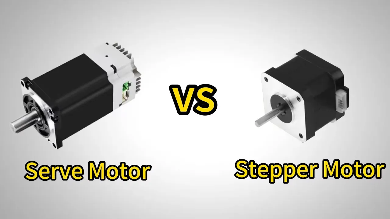
A critical design choice for solar tracking is selecting the right motor. This quick breakdown highlights why high holding torque and precise open-loop step control make steppers highly reliable for heavy outdoor brackets compared to standard hobbyist servos.
Knowledge Checkpoint
- Explain the electrical function of the
STEPpin andDIRpin on an A4988 driver board. - Why is it dangerous to power a NEMA 17 stepper motor directly from the Arduino's 5V board regulator pin?
- Under what mechanical conditions would you choose a stepper motor over a hobbyist servo motor?
Module 5: Algorithm and Logic for Dual-Axis Tracking
Develop the control loop logic that processes light sensor differences and controls the stepper motors. Learn how to implement software calibration techniques to resolve motor jitter and manage coordinate tracking.

Why this video
This video addresses a common issue in solar trackers: motor jitter. It explains how noise in LDR readings causes rapid, unnecessary movements and demonstrates how to resolve this by implementing a software deadband (hysteresis) threshold.

Why this video
This video explains the feedback control logic used in multi-sensor solar tracking. It demonstrates how pairing two identical sensors symmetrically relative to a central shadow-casting divider provides the comparative voltage difference needed to calculate orientation errors.

Why this video
This video breaks down dual-axis tracking logic conceptually: extracting multi-quadrant light sensor information, calculating comparative error offsets, and processing output signals.
Curriculum Gap Alert: Because most hobbyist tutorials focus on basic servo motors, stepper-specific dual-axis code is less common online. When writing your Arduino code, remember:
- Read four analog LDR pins (Top-Left, Top-Right, Bottom-Left, Bottom-Right).
- Calculate the average light levels for the top, bottom, left, and right pairs.
- Determine the differential error between the sides:
Elevation Error = (Top Avg - Bottom Avg)andAzimuth Error = (Left Avg - Right Avg).- Apply Hysteresis: If the absolute error value is below your deadband threshold (e.g.,
< 15), do nothing.- If the error exceeds the threshold, generate a single digital pulse on the A4988 step pin in the direction required to reduce the discrepancy.
Knowledge Checkpoint
- Explain how a physical shadow-casting barrier (divider) between LDR pairs improves sensor sensitivity.
- What is software hysteresis (deadband), and why is it necessary to prevent stepper motor jitter?
- Write out the pseudocode logic for a dual-axis tracking loop using four LDR values.
Module 6: Physical Assembly, Testing, and Calibration
Assemble the physical tracker structure, mount the stepper motors and gear systems, wire your control electronics safely, and calibrate sensor thresholds outdoors.

Why this video
This video demonstrates the physical assembly of a dual-axis solar tracker. It shows how to build robust brackets, mount tracking axes securely, and align your structural frames to prevent mechanical binding.

Why this video
This video outlines how to run physical performance tests on your completed tracker. It demonstrates how to compare a tracking solar panel against a static control panel on cloudless days to measure and log your system's overall efficiency gains.

Why this video
This video demonstrates how to calibrate and test your tracker's movement indoors. By using a benchtop power supply and a flashlight, you can simulate solar movement and test how the tracker responds to different lighting angles in a controlled environment.
Knowledge Checkpoint
- Describe how to test your tracker's functional range of motion safely before taking it outdoors.
- Explain how you would calibrate your LDR code to account for uneven ambient lighting or minor differences between individual sensors.
- Detail a testing plan to measure and compare the daily energy output of your tracking solar panel against a static panel.
Course Map
Key People Index
- Dr. Richard Komp (Solar Physicist / Educator): Prominent researcher in photovoltaic technology, known for simplifying solar cell physics to make renewable energy education accessible globally.
- Paul McWhorter (Robotics and Electronics Educator): A former engineer whose detailed, step-by-step programming and hardware tutorials are a staple of the maker and robotics communities.
- Collin Cunningham (Maker / Hardware Educator): Known for his intuitive visual explanations of electronic components, making complex concepts easy to understand for beginners.
Final Self-Assessment
Complete this comprehensive self-assessment to verify your understanding before deploying your dual-axis solar tracker:
- Solar Physics: I can explain how solar panels convert light to electricity and why maintaining a perpendicular angle to the sun maximizes energy capture.
- Breadboarding: I can build a clean prototyping circuit without overlapping component pins or causing short circuits on the power rails.
- Voltage Dividers: I can design a voltage divider to translate physical light changes at an LDR into variable voltages between 0V and 5V.
- Analog Reading: I can write Arduino code to read analog sensors and convert those readings into consistent digital values.
- Stepper Wiring: I can connect a NEMA 17 stepper motor to an A4988 driver board, including all control, power, and ground connections.
- Driver Protection: I understand how to set the current limit on an A4988 driver to keep my stepper motors running cool and prevent damage to my components.
- Sensor Alignment: I can explain how to divide four LDRs into elevation and azimuth control pairs using a structural divider to cast shadows.
- Hysteresis Implementation: I can write comparative math routines with a defined deadband (hysteresis) to prevent motor jitter under changing light conditions.
- Step Generation: I can write non-blocking code that generates step and direction pulses for the A4988 driver based on LDR light differences.
- Physical Assembly: I can assemble a dual-axis structural frame that moves freely without binding or putting mechanical strain on the motors.
- Controlled Calibration: I can test my tracking logic indoors using a flashlight to simulate solar paths before deploying the system outside.
- Data Logging & Analysis: I can design an outdoor testing setup to measure, record, and compare the energy output of a tracking panel against a static control panel.