Quadcopter Frame: Fusion 360 & 3D Printing
Learning Goal: Design and optimize a lightweight, 3D-printable quadcopter frame using Fusion 360, focusing on structural strength, aerodynamics, and component integration.
This curriculum is designed for hardware designers, drone enthusiasts, and engineers who want to go beyond simple assembly and build their own custom, high-performance, 3D-printed FPV or utility drone frames.
- Prerequisites: Basic familiarity with 3D printers (FDM) and a computer capable of running Autodesk Fusion 360.
- Estimated Total Study Time: 18 hours
Module 1: Quadcopter Fundamentals & Component Integration
Before diving into 3D modeling, you must understand the underlying physics of flight, mechanical layout, and how electronic systems interface. This module covers how quadcopters balance thrust, gravity, torque, and drag, as well as the essential physical and electrical components that must be integrated into your custom frame design.
Video Recommendations
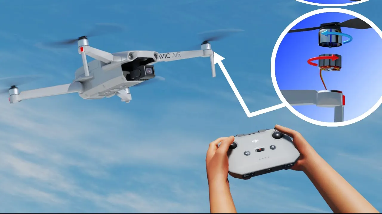
Why this video is valuable: Understanding flight dynamics is essential for frame design. This video breaks down the airfoil principle of propeller thrust and the counter-rotating motor configurations needed to balance torque. It provides the core physics foundation needed to decide on your frame geometry (X vs. H configurations) and how the placement of components affects pitch, roll, and yaw authority.

Why this video is valuable: This video introduces the key hardware components that your frame must accommodate. You will learn about the role of the Flight Controller (FC)—the "brain" containing gyroscopes and accelerometers—and how it interfaces with Electronic Speed Controllers (ESCs), motors, and receivers. Understanding these spatial relationships is critical for designing clean component cavities and wiring channels.

Why this video is valuable: This quick primer highlights the hardware stacking ecosystem. It defines the six essential physical components of a functioning drone: the frame as the structural skeleton, the flight controller, the ESCs, motors, camera systems, and the battery. This sets the stage for creating accurate mockups in your CAD workspace.
Knowledge Checkpoint
- Explain how a quadcopter changes its yaw orientation without altering altitude or pitch.
- Describe the difference in frame stress between an "X-frame" and an "H-frame" configuration.
- Map out the physical wiring connections from the battery, through the ESC, to the FC and motors, ensuring your planned frame layout has enough space for physical wire routing.
Module 2: Fusion 360 CAD Foundations for Drone Design
To design a customized, highly integrated drone frame, you must master parametric modeling within Fusion 360. This module teaches you how to construct sketches, apply constraints, and model precise 3D boundary representations (placeholders) of standard electronics and motors.
Video Recommendations

Why this video is valuable: Your flight controller and ESCs are PCBs that must be securely mounted to your 3D-printed frame. This step-by-step tutorial teaches you how to design modular mounting plates and mounting patterns using standard dimensions. You will learn how to draft parameters, work with standoffs, and ensure safe clearance between electrical traces and printed structural plastic.
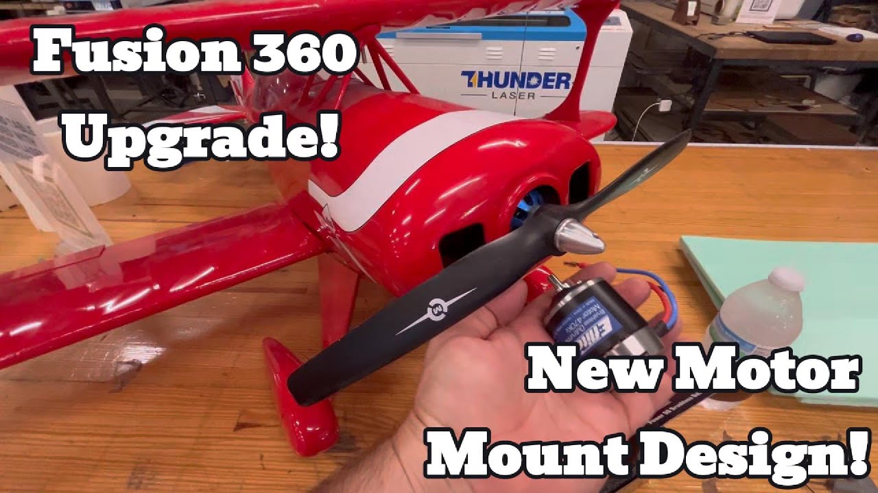
Why this video is valuable: Motors exert high dynamic forces on the frame. This video shows you how to design a custom motor mount while maintaining proper alignment and center of mass. It teaches useful techniques for sketching around specific motor bolt patterns, creating structural reinforcements, and ensuring printability of the mounting holes.
Coverage Gap Note: While these videos provide exceptional foundations for PCB mounting patterns and motor mount geometry, there is no direct step-by-step CAD reference in this module for modeling specific FPV flight controller sizes (such as standard 20x20mm and 30x30mm configurations).
Independent Practice Tip: Before proceeding to Module 3, search for and locate the dimension sheets (technical drawings) of your specific motor (e.g., a standard 2207 brushless motor) and flight controller. Sketch these manually in Fusion 360 as static "component placeholders" to verify your clearances.
Knowledge Checkpoint
- Create a fully constrained sketch of a 30.5mm x 30.5mm mounting pattern with M3 clearance holes.
- Model a 3D placeholder of a brushless motor, including the shaft height, outer bell diameter, and bottom mounting screw patterns.
- Explain the benefits of using parameters (
Modify>Change Parametersin Fusion 360) when designing mounting hole spacing.
Module 3: Frame Geometry & Design for 3D Printing
With the component placeholders ready, you will now design the actual quadcopter frame. You must apply Design for Additive Manufacturing (DfAM) principles, which dictate how part orientation, overhangs, and layer-by-layer adhesion affect the structural integrity of your finished print.
Video Recommendations
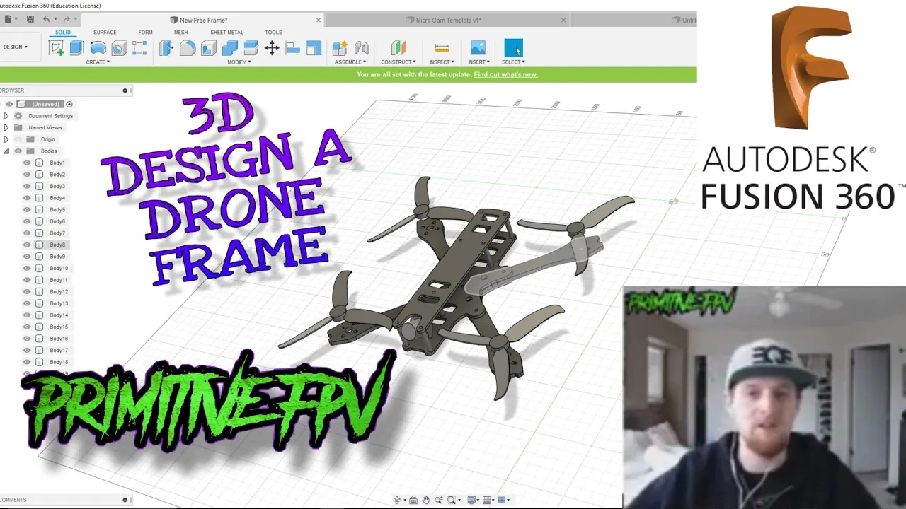
Why this video is valuable: This is a comprehensive, step-by-step workflow showing you how to design a custom multi-rotor frame in Fusion 360. You will learn how to start with propeller clearance sketches, project symmetrical frame arms, design top and bottom plates, and align motor mounts relative to the core flight controller stack.
Why this video is valuable: This video introduces the critical limitations of FDM printing. You will learn how layer lines act as fault lines, why vertical details can be brittle, and how to design with print orientation in mind to ensure the drone arms do not snap along layer boundaries.
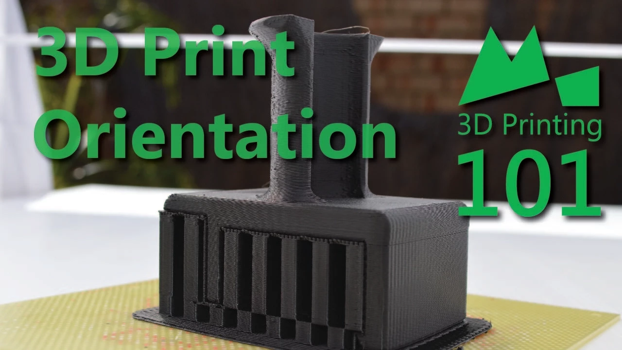
Why this video is valuable: A continuation of printing mechanics, this guide shows you how load direction interacts with print orientation. When designing drone arms, the bending force during high-acceleration maneuvers must run parallel to the continuous extruded lines of plastic, not perpendicular to them.

Why this video is valuable: A highly practical "lessons learned" case study of what goes wrong with fully 3D-printed quadcopters. It shows the assembly of structural frame members, camera angles, wiring channels, and highlights realistic failure modes that you must actively design against (such as arm flexing and motor mount softening).
Knowledge Checkpoint
- Sketch a drone arm layout that ensures the 3D-printed layer lines do not create shear paths perpendicular to the flight forces.
- Identify which surfaces of your frame require support structures, and redesign them with 45-degree chamfers to make them self-supporting.
- Determine how to route your motor ESC wires internally or securely along the arm without exposing them to propeller strikes.
Module 4: Structural Simulation & FEA Optimization
A drone frame must be as lightweight as possible while retaining high rigidity. This module introduces Finite Element Analysis (FEA) and optimization strategies inside Fusion 360 to analyze mechanical stresses, identify weak points under load, and reduce unneeded material.
Video Recommendations

Why this video is valuable: This is the ultimate, beginner-friendly guide to setting up a structural FEA simulation in Fusion 360. You will learn how to set boundary conditions (fixed constraints at the core), apply external forces (thrust loads at the motor mounts), generate a custom computational mesh, and interpret safety factor maps.

Why this video is valuable: Generative design is an incredibly powerful tool for lightweighting parts. This tutorial walks you through setting up design envelopes, identifying "preserved geometries" (such as screw holes and flight controller mount positions), and letting the algorithm generate the lightest possible structural paths linking them together.

Why this video is valuable: This video clarifies the difference between topology optimization and generative design. You will learn how to take a solid, dense frame block and use stress simulations to subtract non-essential material, creating elegant, organic trusses that maintain excellent strength-to-weight ratios.
Knowledge Checkpoint
- Setup a static stress study in Fusion 360 where the motor mounts experience a upward vertical force equal to the total drone mass (to simulate a maneuver).
- Locate the area of highest Von Mises stress on your frame arm and add a custom reinforcement fillet to distribute the stress.
- Define the difference between "preserved geometries" and "obstacle geometries" in a Fusion 360 generative design setup.
Module 5: Aerodynamics & Vibration Mitigation
Even a structurally sound drone will fly poorly if it suffers from massive aerodynamic drag or motor-induced high-frequency vibrations. In this module, you will learn how to design aerodynamic arm cross-sections and soft TPU (Thermoplastic Polyurethane) mounts to protect your flight sensors, as well as select the perfect engineering-grade filaments for your frame.
Video Recommendations
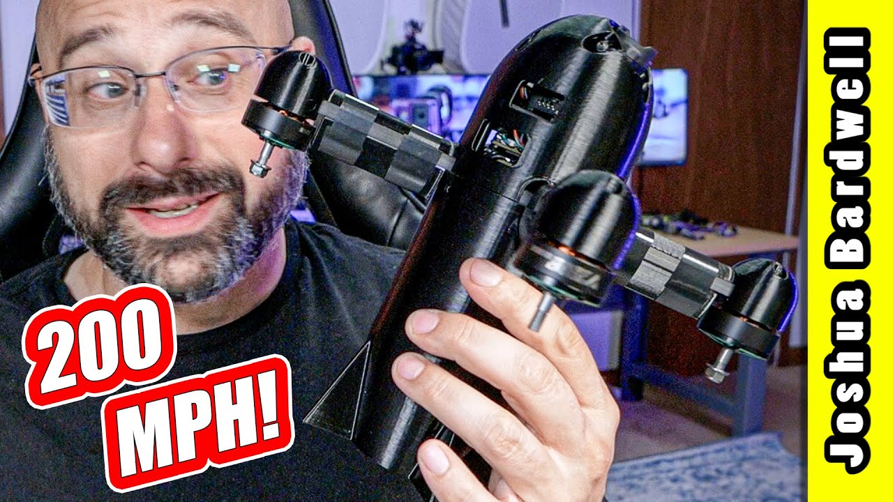
Why this video is valuable: This video covers aerodynamic performance in extreme conditions. It details how adding customized aerodynamic fairings to the rear and underside of the frame arms significantly decreases wake-drag, proving that streamlining the backside of moving objects is just as important as the leading edge.

Why this video is valuable: This video demonstrates the physics of fluid flow around structures. You will see how shifting from cylindrical/blocky shapes (which cause detached, turbulent air wakes) to airfoil shapes drastically reduces drag. You should apply this theory to shape your quadcopter's arms.
Why this video is valuable: High-frequency motor noise can confuse flight controller gyros. This video demonstrates the practical assembly of a 3D-printed vibration-damping system. It shows how combining soft TPU printed pads with mechanical standoffs isolates high-frequency oscillations from the flight camera and sensors.

Why this video is valuable: Selecting the right material is vital. This quantitative testing video compares the actual yield and tensile strengths of PLA, PETG, Nylon, and Carbon-Fiber (CF) Nylon. It debunks common marketing myths and shows how raw stiffness versus impact resistance scales across these filaments.
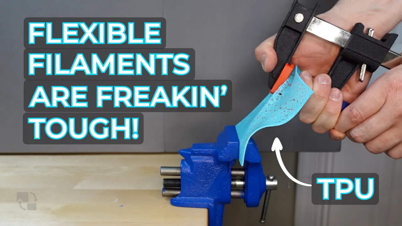
Why this video is valuable: TPU is a crucial material for drone design (used for camera mounts, arm bumpers, and soft mounts). This deep-dive video covers everything from Shore Hardness ratings (e.g., 95A vs. 85A) to the specific printing parameters needed to successfully extrude flexible filaments without jamming.
Knowledge Checkpoint
- Explain how a teardrop or airfoil arm cross-section reduces drag compared to a standard square-extruded arm.
- Design an integrated TPU soft mount in your CAD model to isolate the FPV camera or flight controller stack from the main frame plate.
- Why might standard PLA be poor for long-term outdoor flight frames despite its high static tensile strength? (Hint: consider impact brittleness and thermal resilience in direct sunlight).
Course Map
Below is the recommended sequence of modules. Each step builds the exact pre-requisite knowledge needed to complete the physical and analytical modeling of the quadcopter frame.
Key People Index
The following educators and engineers contributed crucial research, tutorials, and data shown throughout this curriculum:
- Sabin Civil (@SabinCivil): Aerospace physics educator specializing in intuitive visual breakdowns of fluid dynamics and flight mechanics.
- Joshua Bardwell (@JoshuaBardwell): Widely recognized as a leading authority in FPV electronics, drone tuning, and practical aerodynamic optimization.
- Brad Tallis (@bradtallis8968): Professional Fusion 360 application engineer and technical trainer, renowned for structural FEA instruction.
- Angus Deveson (@MakersMuse): 3D printing pioneer whose extensive testing on FDM material behavior and print orientation formed the modern rules of DfAM.
Final Self-Assessment
To verify you have achieved the overall learning goal, check off each of the following practical achievements. If you can complete all of them, your custom drone frame is ready for manufacturing!
- Functional Dimensioning: My Fusion 360 file uses custom parameters to easily adjust mounting hole patterns (e.g., 20x20mm or 30.5x30.5mm) without breaking the model timeline.
- DfAM Optimization: All critical frame components are designed to print without support structures where possible, or they utilize angles sharper than 45 degrees to avoid sagging overhangs.
- Structural Alignment: The printed layer lines of the frame arms are oriented to run parallel to the length of the arm (resisting horizontal bending moments), rather than perpendicular.
- FEA Verification: I have simulated a vertical motor thrust load in the Simulation workspace and verified that the safety factor across all structural areas of the frame is above .
- Topology Refinement: Non-structural bulk material in the center plates of the frame has been systematically pocketed or lightened using generative/topology optimization.
- Aerodynamic Profiling: The arms of the quadcopter frame utilize rounded, teardrop, or chamfered cross-sectional profiles to minimize downward thrust blockages and frontal drag.
- Vibration Isolation: The design includes a specialized soft-mounting mechanism (e.g., TPU landing pads, motor isolators, or dampening rings) to separate high-frequency mechanical noise from the flight controller.
- Material Selection: The chosen print filament balances weight and crash-resilience (e.g., using Carbon Fiber Nylon or highly-tuned PETG for structural plates, and TPU for protective bumpers).