Self-Balancing Robot: Arduino, PID & MPU6050
Learning Goal: Build and program an autonomous, self-balancing two-wheeled robot using an Arduino microcontroller, implementing a PID control loop and sensor fusion with an MPU-6050 IMU.
- Prerequisites: Basic knowledge of electronics (voltage, current, breadboarding) and foundational programming concepts in C++ (variables, loops, conditional statements).
- Estimated Total Study Time: 28 Hours
Module 1: Electronics Foundations & Arduino Motor Control
This module builds the physical and electrical foundation of your robot. You will learn how the Arduino microcontroller functions, write your first basic programs to control I/O pins, and dive into the mechanics of DC motor control. You will understand how H-Bridge drivers (such as the classic L298N) utilize Pulse Width Modulation (PWM) to regulate motor speed and direction from a low-voltage microcontroller.
Recommended Videos

Why this video: For absolute beginners, setting up the integrated development environment (IDE) is the very first barrier. This video takes you through downloading, installing, and interfacing with an Arduino Uno over USB, writing basic code, and uploading it safely. It establishes the basic tooling pipeline you will use throughout the course.
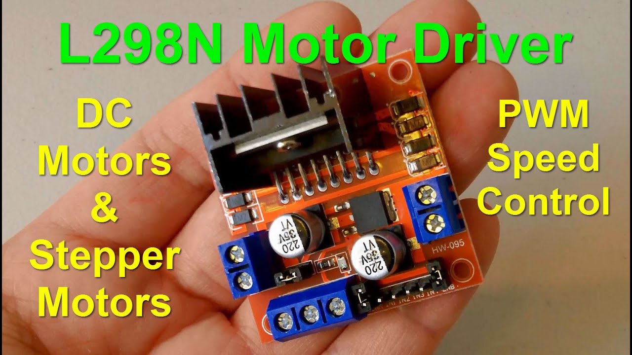
Why this video: You cannot run high-current motors directly from delicate Arduino pins without destroying the microcontroller. This video provides a detailed structural teardown of the L298N Dual H-Bridge module, explaining how it isolates control logic from motor power supplies, interfaces with Arduino control signals, and makes use of onboard voltage regulators.
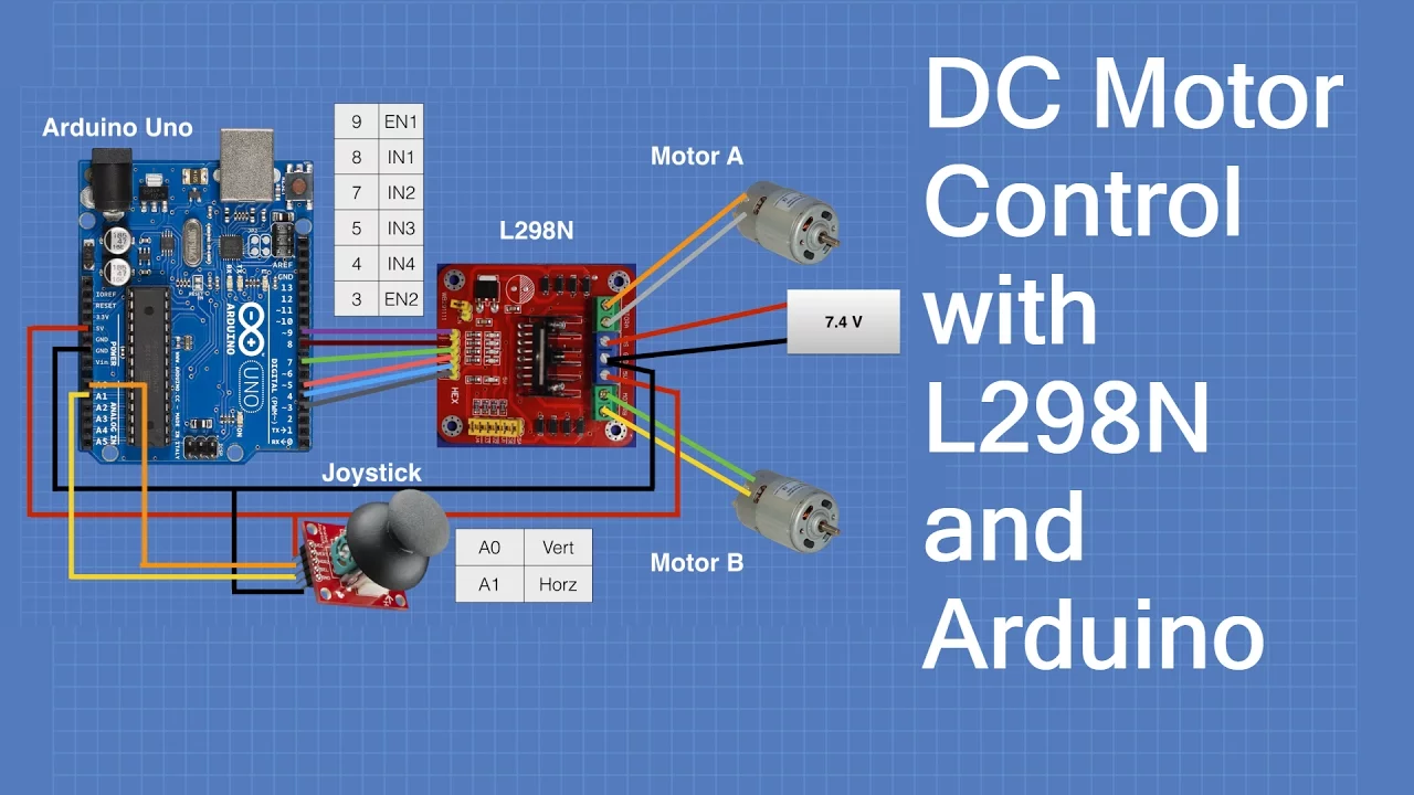
Why this video: This tutorial bridges the gap between hardware and software. It demonstrates how to write C++ code to control both the direction of rotation (via the logic input pins IN1-IN4) and the rotational velocity (via the PWM enable pins ENA and ENB) of two DC motors, providing a practical blueprint for your robot's drive system.
Knowledge Checkpoint
- Install the Arduino IDE and successfully upload a basic sketch (e.g., Blink) to verify hardware communication.
- Understand the role of an H-bridge in reversing DC motor polarity to control direction.
- Explain how Pulse Width Modulation (PWM) changes the average voltage delivered to a motor, altering its speed.
- Draw a basic wiring diagram showing how an external battery supply, an L298N driver, and an Arduino share a common ground.
Module 2: Inertial Measurement Units & Sensor Fusion
A self-balancing robot must continuously calculate its angular deviation from the vertical axis. In this module, you will explore the inner workings of Micro-Electro-Mechanical Systems (MEMS) sensors inside the MPU-6050 Inertial Measurement Unit (IMU). You will interface the sensor using the I2C protocol, read raw data, and implement a complementary filter to resolve raw values into clean, real-time tilt angles.
Recommended Videos
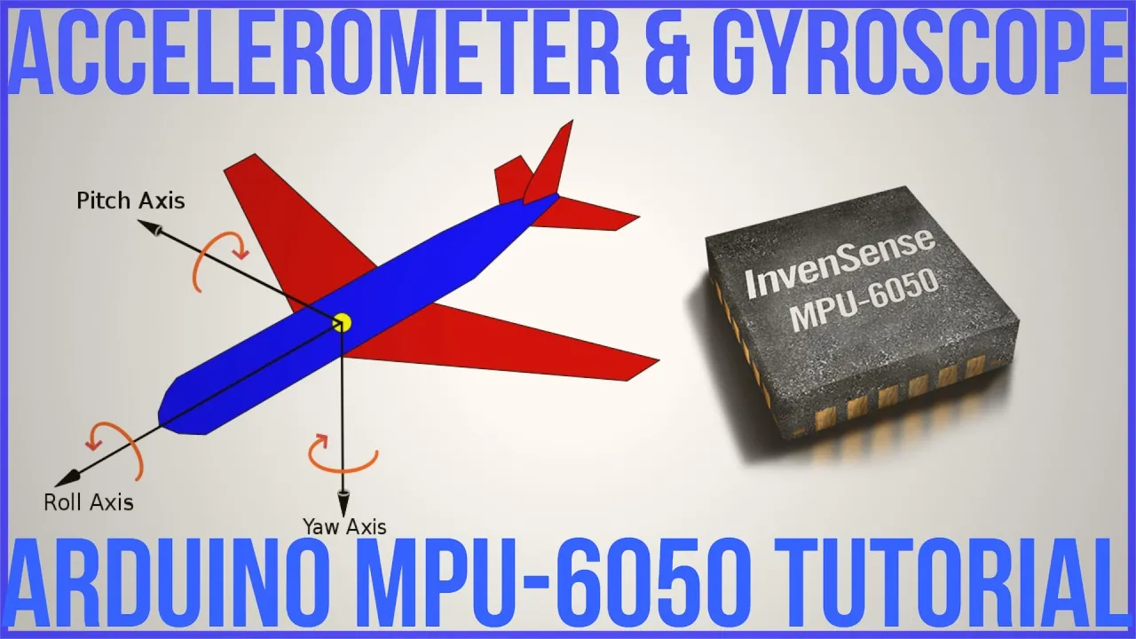
Why this video: This deeply technical tutorial walks through the MPU-6050 register-level architecture. You will learn how to configure the sensor, initiate communications over the I2C bus (SDA and SCL pins), read raw acceleration and angular velocity registers, and translate those registers into physical units (-forces and degrees per second).
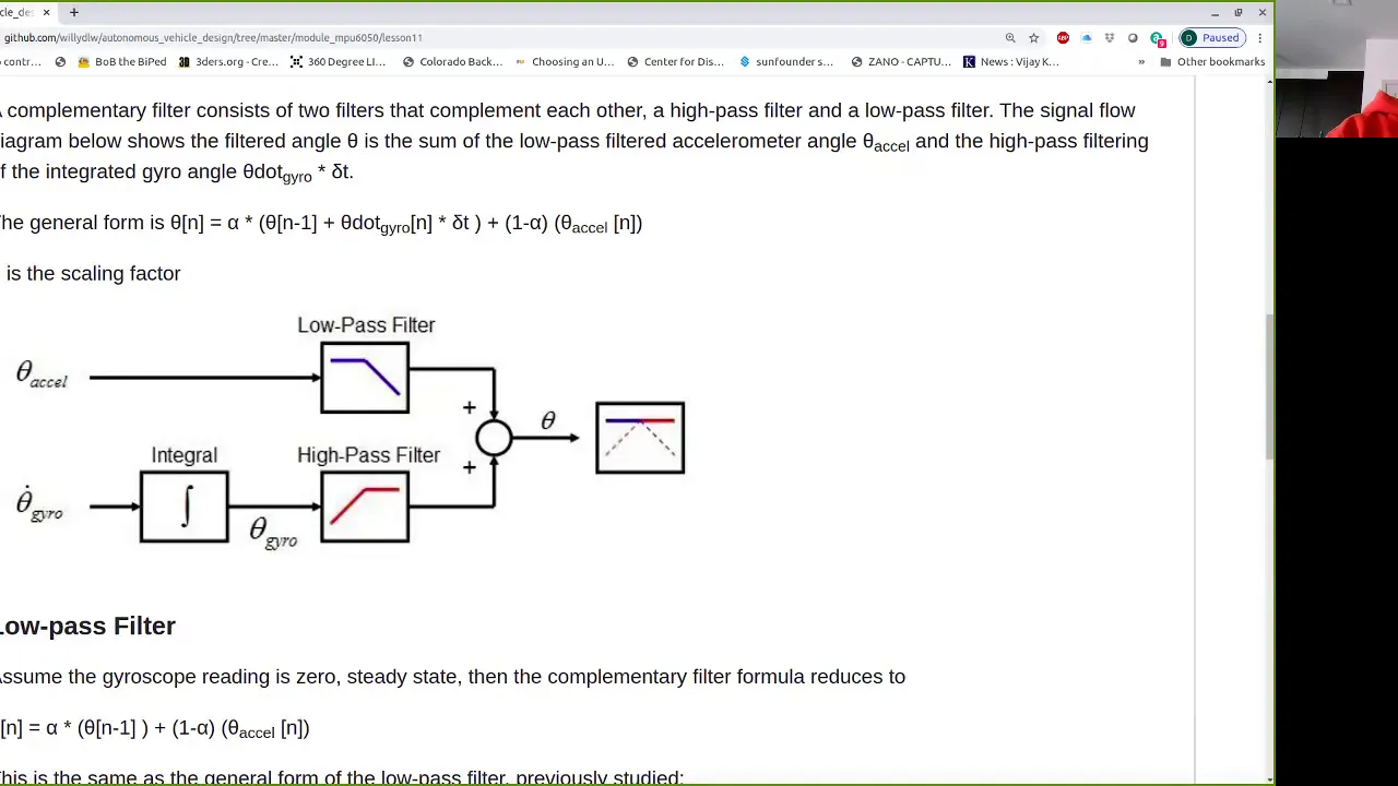
Why this video: Accelerometers suffer from high-frequency vibration noise, while gyroscopes suffer from low-frequency drift over time. This video explains the mathematical theory behind the complementary filter, showing how to balance these two sensors to calculate a reliable angle using a straightforward mathematical equation.

Why this video: This visual comparison demonstrates the raw, unfiltered data versus filtered sensor output on a live display. It highlights how the complementary filter dampens sudden shocks while maintaining zero angular drift over extended operations.
Knowledge Checkpoint
- Connect the MPU-6050 to the Arduino using the hardware I2C interface pins (SDA/SCL) and pull-up resistors.
- Write a sketch that successfully reads raw 16-bit integer values from the MPU-6050 accelerometer and gyroscope registers.
- Explain why a gyroscope's raw output must be integrated over time () to compute change in angle, and why this process introduces drift.
- Implement the complementary filter equation in your Arduino code: where and is gyro angular velocity.
Module 3: Mechanical Design and Chassis Assembly
To balance reliably, a physical robot must conform to strict mechanical constraints. The distribution of mass, structural rigidity, and motor torque are key determinants of control loop stability. Since the video pool has limited dedicated tutorials on physical custom frames, this module supplements existing videos with comprehensive mechanical design rules. You will learn to construct a physical chassis, align its center of gravity, and select high-performance components.
⚠️ Video Pool Gap Notice: High-quality videos detailing step-by-step custom physical assembly for self-balancing robots are scarce in the pool. To bridge this gap, study the structural concepts below and search YouTube for "DIY self balancing robot chassis design physics" and "3D printed self balancing robot assembly" to view additional community-built physical layouts.
Recommended Videos
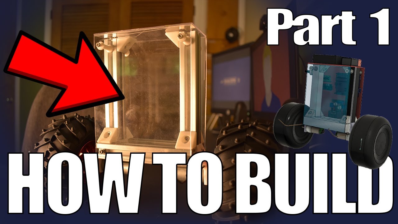
Why this video: This video introduces the core physics of inverted pendulums. The presenter walks you through material selection, torque considerations, physical assembly, and demonstrates why keeping the center of mass high can actually make the robot easier to stabilize.
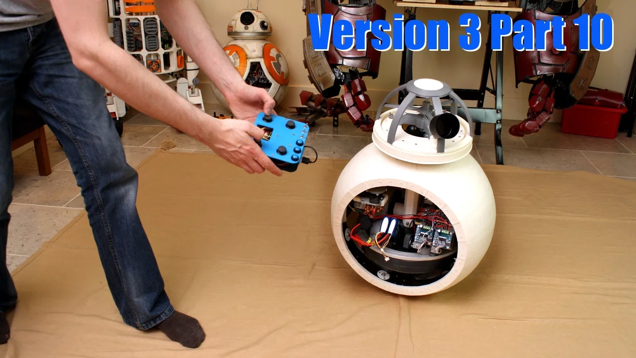
Why this video: Using rapid-prototyping visual examples, maker James Bruton demonstrates how center of gravity (CoG) and mass distribution directly influence tipping limits and oscillatory characteristics, providing intuition on how to distribute physical components on your frame.
Why this video: This video covers practical robot building, mechanical fastening, component alignments, and securing structural plates. These techniques are highly applicable when building stable, rigid platforms for balancing robots.
Structural Design Blueprint
When physical structures flex, they introduce uncontrolled mechanical delay into your feedback loop, which can cause erratic vibrations. Use the following design guidelines to assemble your hardware platform:
+-----------------------------------+ <- TOP LEVEL: Battery (Heavy) & MPU-6050 | [Li-Ion Battery] | (Higher CoG reduces required angular acceleration) | [MPU-6050] | +-----------------------------------+ | | Rigid Threaded Brass Standouts (M3) | +-----------------------------------+ <- MID LEVEL: Arduino Uno & L298N Controller | [Arduino] [L298N] | (Keeps logic board safe from motor noise) +-----------------------------------+ | | Rigid Threaded Brass Standouts (M3) | +===================================+ <- BASE LEVEL: Geared Motors & Wheels | [Motor L] [Motor R] | (Directly coupled to wheels with zero-backlash) +===================================+ (O) (O) <- High-grip rubber or silicone tires
- Center of Gravity (CoG) Elevation: Mount heavy batteries at the top tier of the chassis. While counterintuitive, a taller inverted pendulum falls more slowly, allowing the control loop more time to react.
- Backlash Reduction: Avoid cheap toy motors with loose plastic gears. Use high-quality metal-geared DC motors. Any physical play in the gears (backlash) creates a dead-band where the motors spin but the robot does not move, leading to persistent jitter.
- Sensor Alignment: Mount the MPU-6050 as close to the central vertical axis as possible, oriented perfectly perpendicular to the wheel axis, to ensure rotational accelerations are measured accurately without translating as linear offsets.
Knowledge Checkpoint
- Assemble a rigid, multi-tier chassis using acrylic, plywood, or 3D-printed plates secured with M3 standoffs.
- Verify that there is zero physical play or wobble between the motor shafts and your wheels.
- Position the battery pack at the upper tier of the chassis to raise the center of mass.
- Securely mount the MPU-6050 IMU flat, leveled, and aligned with your drive shaft's centerline.
Module 4: PID Control Theory and Math
This module covers the mathematical foundation of dynamic stabilization: the Proportional-Integral-Derivative (PID) control loop. You will learn how each term computes corrections based on the system's tracking error, explore transfer functions, and study tuning models like the Ziegler-Nichols method to systematically balance your physical system.
Recommended Videos

Why this video: This exceptional math-and-code walkthrough explains how to write a PID algorithm in C++ without relying on external libraries. It explains error tracking, time differential calculation, and how the proportional, integral, and derivative terms are summed to compute the final output.
Why this video: For a rigorous academic understanding, this lecture dissects the mathematical equations and transfer functions of P, I, and D controllers. It explains how each block modifies system response, steady-state error, and transient oscillations.

Why this video: This practical guide visualizes the effects of each parameter (, , ) on a dynamic physical system. It shows how adjusting these coefficients alters response speed, steady-state offset, and overshoot damping.
Mathematical Model
The controller output is computed from the error signal using the following equation:
                            +---------+
                            |  Kp * e |
                       +--->| (Prop)  |---+
                       |    +---------+   |
Setpoint | v (0 deg) Error | +---------+ Sum Control Output [+] ------(X)---------+--->| Ki * ∫e |->[+]--->[To Motors] ^ ^ | | (Integ) | ^ | [-] | +---------+ | | | | | | Filtered | +---------+ | | Angle +--->| Kd * de |--+ | | | (Deriv) | | | +---------+ +---------------+ | MPU-6050 | | (Comp Filter) | +---------------+
- Proportional (): Generates a restorative force proportional to the current tilt angle. If the robot tilts slightly forward, the motors drive slowly forward; if it tilts severely, the motors drive rapidly.
- Integral (): Accumulates persistent errors over time, ensuring the motors run fast enough to overcome static friction and center the robot perfectly rather than settling at a slight tilt.
- Derivative (): Measures the rate of change of the tilt angle to predict future motion, damping oscillations and slowing down motor corrections as the robot approaches center.
Knowledge Checkpoint
- Write down the mathematical equation for a standard PID controller and describe the purpose of each term.
- Understand how numerical integration () and numerical differentiation () are implemented in discrete microcontroller firmware.
- Define "windup" in control systems and explain why limiting the maximum accumulated integral sum is crucial.
- Explain how the , , and parameters influence system stability, rise time, and overshoot.
Module 5: Software Integration and Real-Time Tuning
In this final module, you will combine your MPU-6050 sensor fusion, C++ PID control loops, and motor driver logic into a unified, non-blocking Arduino program. You will implement timed control loops using millis() instead of blocking delays to ensure high-frequency, reliable calculations. You will then manually calibrate and tune your controller coefficients on physical hardware to achieve stable balance.
⚠️ Video Pool Gap Notice: Step-by-step videos demonstrating integrated firmware walkthroughs and empirical PID tuning for physical self-balancing systems are sparse in the pool. To bridge this gap, review the non-blocking software templates and tuning workflows below. Search YouTube for "Arduino non blocking PID control loop tutorial" and "Tuning PID self balancing robot step by step" to see these principles implemented in various community builds.
Recommended Videos

Why this video:
Using the standard delay() function pauses the CPU and halts all program logic. For a self-balancing robot, missing even a few milliseconds of sensor readings or motor corrections can cause it to crash. This video explains how to write non-blocking, time-checked loops using millis().
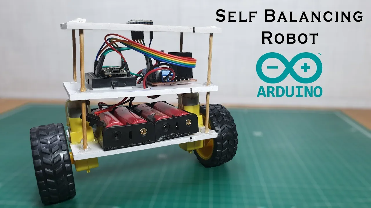
Why this video: This integration overview walks through the physical wiring and complete software architecture of an Arduino-based self-balancing robot. It provides a visual template of how the sensor data, PID calculations, and motor driver outputs operate together in a single workspace.

Why this video: An in-depth, step-by-step tutorial on manually tuning PID loops for an inverted pendulum system. This video demonstrates how to isolate and adjust the , , and gains systematically on physical hardware.
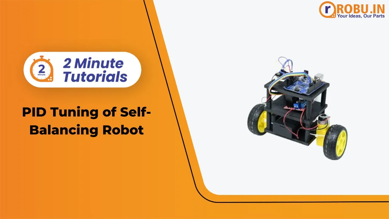
Why this video: This quick tutorial focuses specifically on the interaction of , , and parameters in two-wheeled balancing configurations, providing a reference for troubleshooting oscillations and lag.
Non-Blocking Loop Design
Your control loop must execute at a fixed, reliable rate (e.g., every 10 milliseconds or 100 Hz). This non-blocking C++ template ensures precise timing without interrupting sensor reading or motor execution:
#include <Wire.h>
const unsigned long SAMPLE_TIME_MS = 10; // 100 Hz Control Loop unsigned long lastLoopTime = 0;
float targetAngle = 0.0; // Desired balance point float inputAngle = 0.0; // Filtered angle from MPU-6050 float errorSum = 0.0; float lastError = 0.0;
// PID Tuning Parameters float Kp = 0.0, Ki = 0.0, Kd = 0.0;
void setup() { Wire.begin(); // Configure MPU-6050 & L298N Pins here }
void loop() { unsigned long currentTime = millis();
if (currentTime - lastLoopTime >= SAMPLE_TIME_MS) { float dt = (currentTime - lastLoopTime) / 1000.0; lastLoopTime = currentTime;
// 1. Read IMU Data & Run Complementary Filter
inputAngle = readComplementaryFilterAngle(dt);

// 2. Compute PID Algorithm
float error = targetAngle - inputAngle;
errorSum += error * dt;
errorSum = constrain(errorSum, -200, 200); // Anti-windup
float errorDeriv = (error - lastError) / dt;
lastError = error;

float pidOutput = (Kp * error) + (Ki * errorSum) + (Kd * errorDeriv);

// 3. Drive H-Bridge Motors
driveMotors(pidOutput);
} }
float readComplementaryFilterAngle(float dt) { // Placeholder: Insert complementary filter implementation from Module 2 here return 0.0; }
void driveMotors(float output) { // Placeholder: Insert PWM and pin control from Module 1 here }
Empirical Tuning Guide
Once your code is uploaded, place your robot on a smooth surface and follow this manual tuning procedure:
- Initialize Values: Set , , and .
- Tune Proportional Gain (): Slowly increase in small increments. Hold the robot upright and let go. Continue increasing until the robot begins to oscillate back and forth about the center point. Set to roughly 50% of this threshold value.
- Tune Derivative Gain (): Gradually increase to damp out the oscillations. This term acts like a shock absorber, helping the robot recover smoothly when tilted. Increase until any rapid jitter or high-frequency shaking is introduced, then back it off slightly.
- Tune Integral Gain (): If the robot balances but slowly drifts away in one direction, increase in small increments. This will increase motor drive to overcome static friction and keep the robot centered.
Knowledge Checkpoint
- Explain why using
delay()inside your main control loop causes system instability. - Implement a timed, non-blocking executive loop using
millis()running at a constant frequency (e.g., 100 Hz). - Implement an anti-windup clamping threshold on your accumulated integral error.
- Systematically tune , , and parameters on your physical robot to achieve upright balance.
Course Map
This flowchart maps the optimal path through the modules. You should build the physical frame and master sensor reading before diving into control theory and tuning.
Key People Index
The following engineers, educators, and makers are featured in this curriculum:
- Vlad Romanov (@VladRomanov89): An electronics engineer who specializes in explaining the architecture and programming of register-level motion sensors, such as the MPU-6050.
- James Bruton (@jamesbruton): A former toy designer and robotics maker known for his experimental designs and explanations of robot physics, balance systems, and center of gravity dynamics.
- Carey Ian (@careyian): A systems designer who breaks down mathematical algorithms and control structures into accessible, custom C++ code.
- DroneBot Workshop (@Dronebotworkshop): An educational channel focused on open-source hardware, motor controllers, and step-by-step breadboard wiring tutorials.
Final Self-Assessment
Complete these tasks to verify that your robot is fully functional and stable:
- Power Safety: Your robot's motor power and logic power circuits must share a common ground, with all wires neatly secured to prevent short circuits.
- Rigid Chassis: The robot frame must be mechanically rigid, with zero play or flex in the standoffs or motor mounts.
- CoG Check: The battery is mounted at the upper tier of the chassis, and the MPU-6050 is mounted flat, centered, and level.
- Sensor Fusion Validation: The complementary filter reliably outputs zero degrees when the robot is held perfectly vertical, with minimal noise and no drift over time.
- Non-Blocking Execution: The main loop runs at a fixed, reliable rate (e.g., 100 Hz) using
millis()with zero blocking delays. - Anti-Windup Protection: Your code restricts the maximum value of the integrated error sum to prevent runaway motor drive when the robot is held tilted.
- Stable Balance: The robot can balance upright on a flat surface for at least 60 seconds without drifting away or falling over.
- Recovery from Disturbance: When gently nudged or pushed, the robot drives to correct itself, dampening any oscillations to return to a stable, upright state.