Planetary Gearboxes: CAD, Backlash & Torque
Learning Goal: Design and assemble a high-reduction planetary gearbox using CAD, calculating gear ratios and backlash, and measuring torque transmission efficiency.
- Prerequisites: Basic algebra, introductory 3D CAD modeling experience (Fusion 360 or SolidWorks), and basic mechanical physics concepts (torque, RPM, power).
- Estimated Total Study Time: 22 hours
Module 1: Gear Fundamentals & Planetary Mathematics
This module covers the core mathematical and physical principles of gears. You will explore fundamental gear terminology, differentiate between metric module and imperial pitch, and master the kinematic math of epicyclic (planetary) gear trains. By the end of this module, you will be able to calculate precise planetary gear reduction ratios for any configuration of sun, planet, and ring gears.
Recommended Videos
- Why this video: This video introduces essential gear terminology, clarifying the difference between metric Module () and imperial Diametral Pitch (). It explains why gears cannot be sized purely by their physical outer diameters and establishes the foundational parameters required for CAD-based gear generation.

- Why this video: This conceptual overview explains how a planetary gear system operates, showing how the sun, planet, and ring gears interact. It visualizes how compact, lightweight designs achieve high torque and high gear ratios.
- Why this video: A practical walkthrough of the fundamental planetary gear ratio formula. It shows how holding different elements stationary (such as the ring gear or the sun gear) changes the overall gear ratio and direction of rotation.

- Why this video: This video derives the mathematical planetary gear formula using linear and angular velocities. It provides the deep analytical foundation needed to calculate ratios when multiple inputs are moving, confirming the formula:
Knowledge Checkpoint
- Explain the physical meaning of "Module" () and how it relates to pitch diameter () and tooth count ().
- Calculate the gear ratio of a planetary set with a 12-tooth sun gear and a 60-tooth ring gear when the ring is held stationary and the sun is the input.
- Describe how the planet carrier's rotational speed relates mathematically to the speed of the sun gear and ring gear.
Module 2: CAD Modeling & Gear Generation
This module transitions from theory to virtual execution. You will learn to generate accurate involute spur gear tooth profiles using built-in scripts and equation-driven curves in SolidWorks and Fusion 360. You will construct a complete, parametric planetary assembly with functional mates to prepare for structural testing.
Recommended Videos
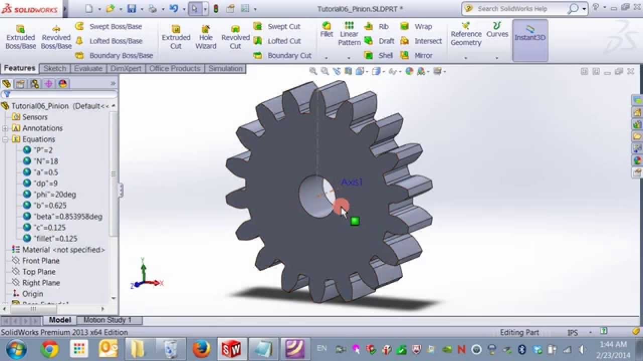
- Why this video: True mechanical gears require an involute curve profile to transmit torque smoothly without binding. This deep-dive video teaches you how to construct mathematically perfect gear teeth in SolidWorks using parametric equations.

- Why this video: A comprehensive, step-by-step tutorial on modeling a complete planetary gear set in Fusion 360. It covers defining parameters, building the ring gear, positioning the planet gears at correct pitch circle distances, and animating the final assembly.

- Why this video: This quick tutorial explains how to use Fusion 360's built-in Python script utilities (found under Utilities > Add-ins > Scripts) to automatically generate spur gears. This utility saves time when rapid prototyping different module sizes.
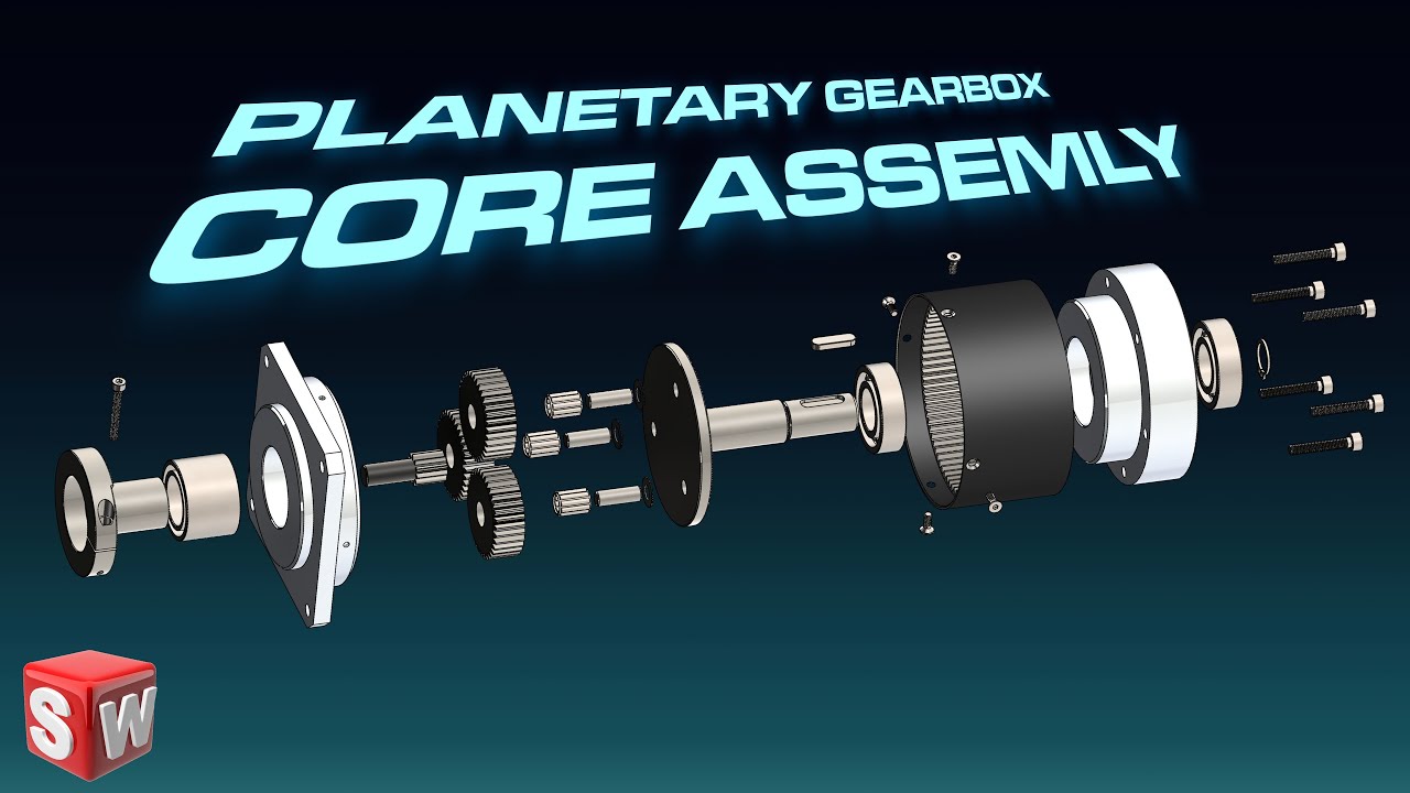
- Why this video: Focuses on the final assembly of a planetary gearbox in SolidWorks. You will learn to mate the sun gear, carrier plate, planet pins, and ring gear casing to ensure correct mechanical movement and check for physical interference.
Knowledge Checkpoint
- Generate an involute spur gear in your chosen CAD tool using a mathematical script or toolset.
- Calculate the correct center-to-center distance () between the sun and planet gears using their tooth counts and module:
- Assemble your CAD model and apply rotational gear mates to demonstrate movement.
Module 3: Backlash Control & Tolerancing
In real precision machinery, perfect theoretical CAD dimensions lead to failure due to manufacturing tolerances and thermal expansion. This module covers backlash—the clearance between mating teeth—and introduces profile shifting to prevent tooth undercutting in high-reduction, small-pinion gearboxes.
Recommended Videos

- Why this video: This video explains the physics of gear backlash and its relationship to shaft center distance. It demonstrates how too little clearance causes binding and high friction, while too much clearance introduces rotational play.
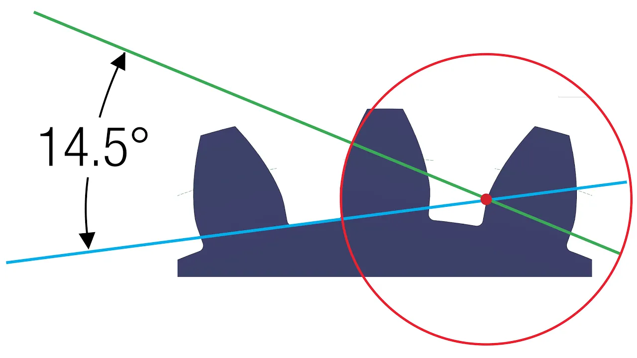
- Why this video: Shows how to directly input backlash parameters within CAD generation tools. It explains how pressure angle changes the strength of the tooth profile and affects the clearance needed between mating teeth.

- Why this video: A concise explanation of "profile shifting" (or tooth geometry modification) by moving the cutting tool/profile relative to the pitch circle axis. This technique is useful when modeling small sun gears to prevent structural weakening.

- Why this video: Focuses on the rule of thumb for profile shifting: when a pinion has 18 or fewer teeth, standard geometry causes undercutting. A positive profile shift must be calculated and modeled to ensure proper clearance and maintain tooth strength.
Knowledge Checkpoint
- Define backlash in arcminutes and calculate how linear play at the pitch circle translates to rotational play on the output shaft.
- Determine when a gear profile shift is mathematically required for a small pinion gear.
- Adjust the center-to-center distance of your planetary gear carrier in CAD to introduce a designated backlash clearance (e.g., to for 3D printing).
Module 4: Fabrication, Bearings & Assembly
This module covers the physical fabrication of your gearbox. You will learn optimal slicing configurations for high-strength FDM 3D printing, trace the physical assembly workflow, and select rolling-element bearings to support the high axial and radial loads generated in high-reduction systems.
Recommended Videos

- Why this video: A comprehensive guide to fabricating functional planetary gearboxes using 3D printers. It covers scaling adjustments, slicer infill density (recommending at least 50% for mechanical structural components), material selection, and troubleshooting assembly binding.
- Why this video: Demonstrates how to choose the right bearing for mechanical design. It covers selecting bore profiles (hex vs. round), choosing flanged bearings to lock positioning in gearbox casings, and evaluating radial vs. thrust loads.

- Why this video: Shows a clean, step-by-step physical assembly of a motor-driven planetary gearbox. It demonstrates how to press-fit bearings, secure planetary pins, mount input motor shafts, and apply lubricant to reduce thermal wear.
Knowledge Checkpoint
- Select appropriate 3D printing parameters (infill density, wall line count, and print orientation) to maximize the shear strength of gear teeth.
- Select a bearing from a manufacturer catalog (e.g., a standard deep-groove ball bearing) that meets the calculated radial load of your output carrier.
- Assemble your printed parts, ensuring that the sun, planet, and carrier plates are aligned without catching or binding.
Module 5: Torque Testing & Efficiency Measurement
Your gearbox is assembled, but how efficient is it? In this module, you will construct a torque testing rig and use mechanical calculations to measure real-world transmission efficiency. You will isolate friction, calculate load capacity, and plot mechanical losses across different operating speeds.
Recommended Videos
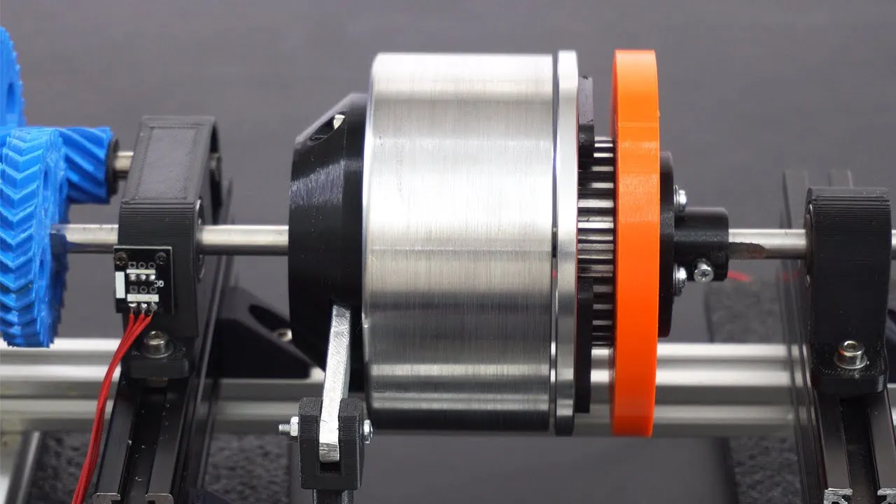
- Why this video: An excellent tutorial on measuring gearbox efficiency. It explains how to set up an experimental rig to measure input mechanical power vs. output mechanical power using the formula: It also details the use of a load cell for torque and a Hall effect sensor for measuring rotational speed (RPM).

- Why this video: Demonstrates the construction of a custom, low-cost dynamometer. It shows how to pair an optical encoder for speed measurement with a load cell braking arm to capture precise, real-time torque output curves.
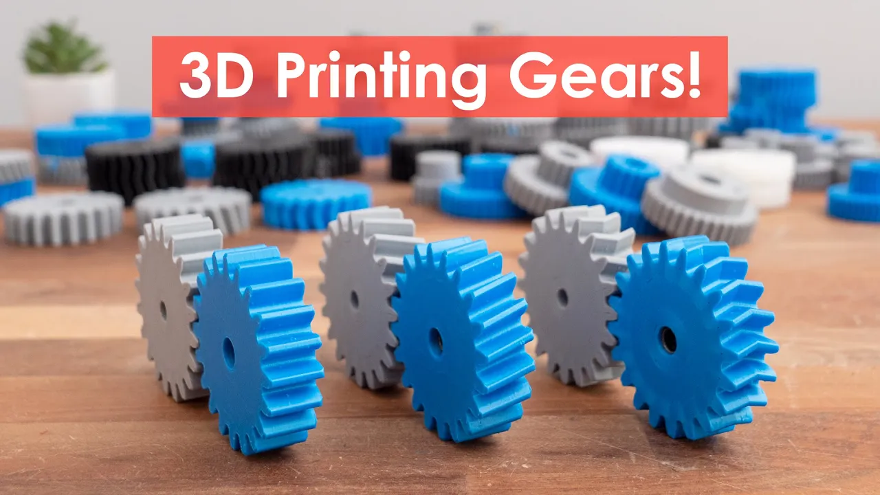
- Why this video: Shows how to run a load test on 3D-printed gears. It outlines how to apply a controlled electrical load to an input motor and measure the resulting physical force generated at the gearbox's output shaft.

- Why this video: Details how to test "holding torque" and structural limits. It shows how to mount measured weights at set distances along a lever arm to calculate maximum holding torque before gear slippage or physical tooth failure occurs.
Knowledge Checkpoint
- Build a test rig using a lever arm and a force scale or load cell to measure output torque ().
- Measure the input voltage and current of your drive motor, calculate electrical power input, and compare it against mechanical output power.
- Calculate the transmission efficiency () of your gearbox using:
- Identify the main sources of power loss (e.g., friction between gear teeth, bearing drag, or frame deflection).
Course Map
This map outlines the recommended progression through the curriculum, starting with core math, moving through CAD modeling and tolerancing, and ending with physical assembly and dynamometer testing.
Key People Index
- Tony (@ThisOldTony): Maker and machining educator known for explaining gear parameters, sizing standards, and fabrication physics clearly.
- Prof. Dr.-Ing. Christian Rieg: German academic and mechanical engineering designer who specializes in gear machining, profile shifting, and tool paths.
- James Bruton: Robotics engineer and former toy designer who models, 3D prints, and tests high-torque actuators, gearboxes, and custom cycloidal/planetary drives.
Final Self-Assessment
Complete this comprehensive self-assessment to verify that you have met all the requirements of the learning goal:
- Planetary Calculations: You can calculate the exact gear reduction ratio of any planetary gear set using the tooth counts of the sun and ring gears.
- Pitch Compatibility: You can verify that the sun, planet, and ring gears share the same module () or diametral pitch () and pressure angle for correct meshing.
- CAD Modeling: You have generated mathematically accurate involute gear profiles in CAD (Fusion 360, SolidWorks, or similar) rather than using simplified cylinders.
- Backlash Design: You have designed a target backlash clearance (e.g., to ) into your CAD model to prevent gear binding after fabrication.
- Profile Shifting: You can explain when a profile shift is needed on a small sun gear to prevent tooth undercutting, and you can model this shift in CAD.
- Fabrication Slicing: You have configured print settings (wall line count, infill percentage, and material choice) to withstand high mechanical load requirements.
- Bearing Integration: Your final assembly uses rolling-element ball bearings to support radial loads and prevent shafts from deflecting under load.
- Friction Mitigation: Your assembled gearbox rotates smoothly by hand without tight spots, high friction, or gear binding.
- Torque Testing: You have built a physical test setup (such as a torque arm with a load cell or weight hangers) to measure output torque.
- Efficiency Calculation: You have calculated your planetary gearbox's mechanical efficiency () by measuring and comparing its input and output power.