Designing a 5V PCB: KiCad, Layout & Assembly
Learning Goal: Design, layout, and assemble a custom 5V regulated linear power supply PCB using KiCad, focusing on schematic capture, component selection, thermal management, and hand-soldering.
Prerequisites
- Basic familiarity with passive electronic components (resistors, capacitors, diodes).
- Access to a computer capable of running KiCad (v7.0 or v8.0).
- A hand-soldering iron station and basic protective gear.
Estimated Total Study Time
16 Hours (incorporating video instruction, self-paced software design, thermal calculations, and hands-on assembly).
Module 1: Power Supply Fundamentals & Linear Regulation
This module establishes the foundational electronics knowledge required to design a reliable power supply. You will study how raw alternating current (AC) is stepped down, rectified into direct current (DC), filtered to eliminate voltage ripple, and stabilized using a linear regulator like the LM7805.
Recommended Videos
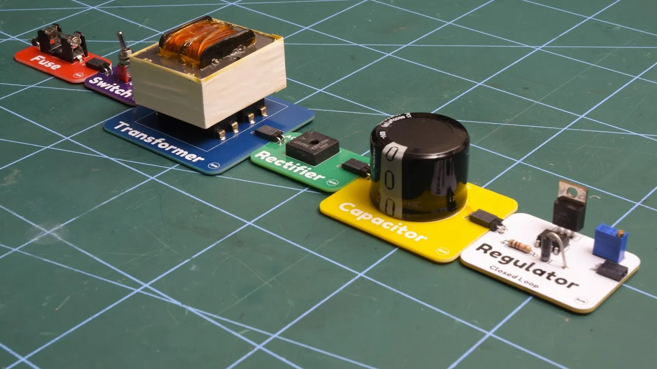
- Why this video is valuable: This video provides an exhaustive, top-to-bottom breakdown of the five distinct stages of a linear power supply: the AC mains input, transformer isolation, bridge rectification, capacitor smoothing, and final regulation. It acts as the conceptual anchor for this entire curriculum.

- Why this video is valuable: Eugene Khutoryansky's highly visual, intuitive animations illustrate exactly how electrical currents move through individual diodes, full bridge rectifiers, and filtering capacitors. It is critical for mastering the mechanics of AC-to-DC conversion.

- Why this video is valuable: This video bridges theory and practical component selection. You will learn the mathematical formulas required to select electrolytic filter capacitors and diodes with appropriate safety margins (voltage and current ratings) to prevent component failure.
- Why this video is valuable: A concise overview of the industry-standard LM7805 linear regulator. It introduces the role of polarized input and output ceramic/electrolytic capacitors in suppressing high-frequency oscillations and stabilizing output.
Module 1 Knowledge Checkpoint
- Can you sketch and explain the five distinct stages of a linear regulated power supply?
- Why does a full-bridge rectifier require four diodes, and how do they alternate conduction over positive and negative AC half-cycles?
- How does an electrolytic capacitor smooth out pulsating DC ripple voltage, and how do you calculate the minimum capacitor value?
- What is the function of the decoupling capacitors placed directly adjacent to the input and output pins of the LM7805 regulator?
Module 2: Schematic Capture in KiCad
In this module, you will translate your theoretical paper design into a digital schematic using KiCad. You will learn component search strategies, symbol placement, wiring conventions, net flagging, and how to use the Electrical Rules Checker (ERC) to eliminate errors before designing the PCB layout.
Recommended Videos
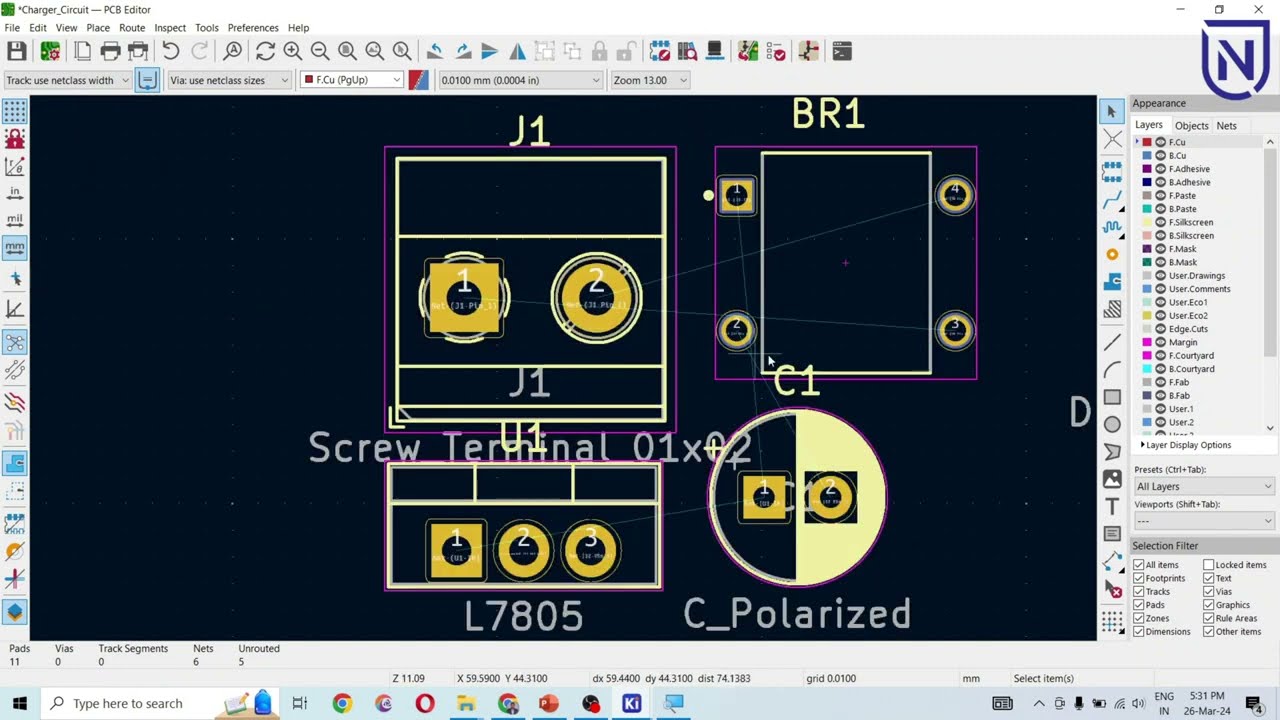
- Why this video is valuable: This video guides you through the complete creation of a 5V power supply circuit directly within the KiCad environment. It details the step-by-step schematic capture process, including adding connectors, bridge rectifiers, and filter capacitors.
- Why this video is valuable: This video provides an overview of professional design workflows within KiCad, emphasizing structural schematic design, standard keyboard shortcuts (e.g.,
Afor add,Rfor rotate,Wfor wire), and organizing symbols systematically.

- Why this video is valuable: Pin conflicts and unconnected pins are among the most common design mistakes. This video teaches you how to run KiCad's Electrical Rules Checker (ERC), interpret warning/error flags, and use power flags (
PWR_FLAG) to resolve unresolved power net errors.
Module 2 Knowledge Checkpoint
- Do you know the critical KiCad keyboard shortcuts for adding component symbols (
A), routing wires (W), editing values (V), and rotating symbols (R)? - What is the purpose of the Electrical Rules Checker (ERC), and how do you resolve an "Input Pin not driven by any Power Source Pin" error?
- How do you assign specific footprints to physical components in KiCad using the footprint association tool?
- Why is it essential to annotate schematic designators (e.g., changing
C?toC1,C2) before moving to board layout?
Module 3: Thermal Management & Component Sourcing
Note: In electronic design, thermal calculations and component selection must be completed before starting the physical PCB layout. Heatsink dimensions, packages, and footprint sizes heavily dictate trace sizing, thermal vias, and board space.
This module teaches you how to read datasheets to extract electrical characteristics, calculate power dissipation, and design thermal solutions. You will calculate regulator temperatures to determine if your PCB design requires thermal vias or passive heatsinks.
Recommended Videos
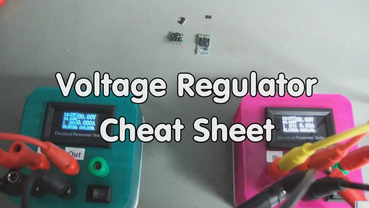
- Why this video is valuable: Andreas Spiess explains linear regulator power dissipation using thermal resistance values () in . He illustrates how a tiny SOT-223 package can quickly overheat at relatively low currents, proving why thermal math is critical during component selection.

- Why this video is valuable: This video shows the core linear regulator thermal formula: . It explains how heat rise limits output current, demonstrating how to select a heatsink using thermal resistance metrics.

- Why this video is valuable: Learning to navigate datasheets is a vital skill. This guide explains how to read electronic datasheets to verify pinouts, thermal thresholds, maximum input voltages, and packages.

- Why this video is valuable: Dave Jones teaches you how to dissipate heat from surface mount devices (SMD) directly through the copper layers of a PCB. He covers thermal resistance matching, thermal vias, and copper thermal pad geometry.
Deep Dive: Linear Regulator Thermal Math
Before continuing, make sure you can calculate the thermal characteristics of your 5V power supply:
Where:
- = Power dissipated as heat (Watts).
- = DC voltage entering the regulator (e.g., from a rectified transformer output).
- = Regulated voltage ().
- = Operating current of your circuit (e.g., ).
- = Internal semiconductor junction temperature (must not exceed maximum rating, typically ).
- = Ambient operating temperature (typically room temp).
- = Junction-to-Ambient thermal resistance of the package (e.g., for TO-220 packages without a heatsink).
If calculated , you must attach a heatsink with a low thermal resistance () or optimize your PCB copper pour with thermal stitching vias.
Module 3 Knowledge Checkpoint
- If your rectified input voltage is , output is , and current draw is , how many watts of power is your linear regulator wasting as pure heat?
- If a regulator's datasheet lists , and you are dissipating at an ambient temperature of , what is the junction temperature? Do you need a heatsink?
- What is the physical role of a thermal via, and how does stitch-routing it to back-side copper planes improve heat dissipation?
- Where do you locate key thermal characteristics (like max junction temp and package thermal resistances) within an IC datasheet?
Module 4: PCB Layout, Routing, and Power Planes
With your components chosen and thermal strategy set, you are ready to design the physical circuit board. You will learn to route traces, manage board outlines, group components by function, set trace widths for higher current carrying capacities, and create solid ground planes.
Recommended Videos

- Why this video is valuable: This video explains how to lay out components to avoid ground loops. You will learn why following the schematic layout directly can lead to physical routing issues and how to arrange components to optimize current pathways.
- Why this video is valuable: Standard signal traces (typically 0.2mm - 0.25mm) are too thin to carry power supply currents without heating up. This tutorial shows how to configure constraints, clearances, and Net Classes in KiCad to assign thicker traces specifically to power lines.

- Why this video is valuable: This live-design highlight emphasizes manual routing over auto-routing. It demonstrates how to route power connections first with wide traces, use 45-degree trace bends, and configure a large, low-impedance ground plane copper fill.

- Why this video is valuable: Once your physical layout is complete, you must export it for manufacturing. This tutorial shows you how to export Gerber files, drill files, silkscreen configurations, and solder mask files from KiCad's Plot dialog.
Deep Dive: KiCad Trace Widths for Power Traces
To prevent overheating, trace widths must match the expected current draw. In KiCad, open the built-in Calculator Tool and select the Track Width tab:
- Input your target current (e.g., max current).
- Input your acceptable temperature rise (typically ).
- Input the copper thickness of your board (standard is , which equals approximately or ).
- The calculator yields the minimum track width (e.g., roughly or for a run on an external layer).
- In KiCad's Board Setup, define a "Power" Net class with this width, applying it directly to your voltage rail net.
Module 4 Knowledge Checkpoint
- How do you determine the minimum width of a PCB trace that must carry 2.0A of current?
- Why should high-frequency/power traces use 45-degree angles instead of sharp 90-degree corners?
- What is a ground plane, and how does creating a large copper pour zone on the bottom layer improve signal integrity and simplify routing?
- Which file outputs are required to order your boards from a modern PCB manufacturer? (Hint: List the Gerber layer extensions).
Module 5: Hand-Soldering, Assembly, and Safe Testing
This final module focuses on physical assembly and verification. You will learn hand-soldering techniques, joint inspection, and how to safely run the first power-up test using a multimeter and a current-limited power source to prevent short circuits.
Recommended Videos

- Why this video is valuable: This video demonstrates hands-on soldering techniques for both through-hole and surface-mount components. It focuses on heat application, joint preparation, and how to feed solder safely to create clean, reliable joints.

- Why this video is valuable: Dave Jones teaches you how to identify high-quality solder joints and fix common mistakes. You will learn to recognize dry joints, cold joints, and bridges, as well as how to use desoldering braid to clear excess solder.

- Why this video is valuable: This video details the complete assembly and safety testing sequence for a newly built power supply board. It introduces safety devices like the "dim bulb tester" to protect components from overcurrent damage during initial power-up.
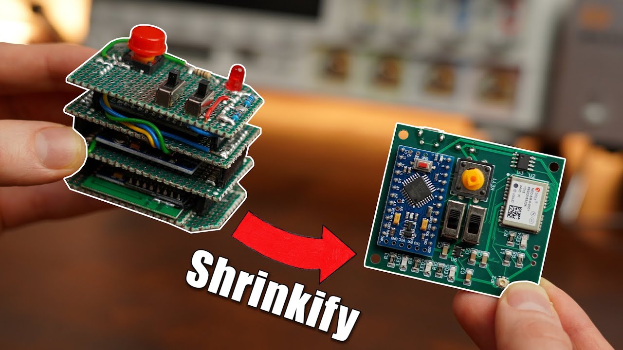
- Why this video is valuable: This short video details a standard post-assembly checklist: testing for shorts between bare pins, verifying polarity orientation, powering on with a current-limited bench power supply, and monitoring current draw.
The Safe "First Power-Up" Protocol
To safely test a newly assembled power supply board, follow this step-by-step procedure:
- Visual QC: Use a magnifying glass to inspect the board. Check that all electrolytic capacitors, diodes, and the regulator are aligned with their proper polarities.
- Cold Multimeter Testing: Before applying power, set your digital multimeter to the Continuity Mode (buzzer).
- Probe the input terminals ( to ) and the output terminals ( to ).
- If your multimeter beeps, there is a physical short on your board. You must find and remove the solder bridge before powering on.
- Current-Limited Powering: Do not plug your supply directly into a raw wall adapter for its first test. Connect it to a laboratory bench power supply with the current limit set low (e.g., to ). If a short remains, the bench supply will clip to current-limit mode, protecting your components.
- Voltage Verification: While powered, set your multimeter to DC voltage mode. Measure the voltage across your output terminals. It should read a stable value between and .
Module 5 Knowledge Checkpoint
- What are the characteristics of an ideal solder joint? (How does it look compared to a cold or dry solder joint?)
- How do you configure a multimeter to check for an input-to-output short circuit before applying power?
- Why is it dangerous to power up a newly assembled PCB using a high-current adapter without testing it first?
- If your LM7805 output voltage reads significantly lower than 5V (or reads 0V) during testing, what are the first three things you should check?
Course Map
This flowchart shows the recommended order of modules and their dependencies:
Key People Index
- Dave Jones (@EEVblog): An experienced electronics design engineer and educator. His videos are valuable resources for hand-soldering techniques, board debugging, and physical thermal layout design.
- Eugene Khutoryansky (@EugeneKhutoryansky): An educator known for his detailed, intuitive animations. His work simplifies complex electromagnetic and electrical concepts.
- Andreas Spiess (@AndreasSpiess): A Swiss engineer and educator known as "the guy with the Swiss accent." He produces highly practical content focused on component selection, thermal limits, and microcontroller prototyping.
Final Self-Assessment
Test your understanding of the complete design process with this self-assessment:
- I can explain the function of each stage in a linear power supply (AC input, transformer, rectifier, filter capacitor, regulator).
- I can search for components in KiCad, place symbols, route wires, and run the Electrical Rules Checker (ERC) to fix schematic errors.
- I can read a datasheet to find the thermal resistance () and maximum junction temperature () of a linear regulator.
- I can calculate expected regulator power dissipation using and determine if my design requires a heatsink.
- I can use KiCad's Calculator Tool to determine track widths based on expected current limits and temperature rise.
- I can route thick power traces and create a solid ground plane to ensure stable power delivery.
- I can export Gerber files, drill files, and assembly drawings from KiCad.
- I can solder through-hole and SMD components, creating clean, shiny joints without cold joints or solder bridges.
- I can run cold continuity checks with a multimeter to verify there are no short circuits before powering on a board.
- I can safely power up and verify a stable 5V output using a current-limited source.