Robotic Arms: Kinematics, OpenCV & Control
Learning Goal: Design, simulate, and program a 3-axis robotic arm to perform automated sorting using inverse kinematics and computer vision (OpenCV) for object detection.
- Prerequisites: High school physics (basic mechanics and vector math), trigonometry, and an introduction to basic programming concepts.
- Estimated Total Study Time: 48 hours
Module 1: Foundations of Python & Microcontrollers for Robotics
This module establishes the core hardware and software foundations necessary for robotics. You will learn the basics of Python programming structured for robotic systems, interface with microcontrollers, prototype circuits using breadboards, and master physical motor actuation. A critical focus of this module is understanding Pulse-Width Modulation (PWM) and multi-channel servo control using the PCA9685 driver board to drive multi-axis systems without overloading microcontroller pins.
Recommended Videos
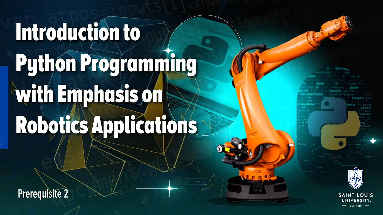
- Why this video: This lecture serves as the absolute software baseline. Instead of generic Python scripting, it directly targets data types, control loops, and data structures (such as lists, tuples, and dictionaries) in the context of robot manipulation, motion planning, and handling sensor coordinates.
- Knowledge Checkpoint:
- Write a Python script that stores 3D target coordinates as tuples inside a list and loops through them.
- Define custom functions that take variable inputs (like angles) and return processed commands.
- Demonstrate how to manipulate arrays and dictionaries to store state representations of a robot's joints.

- Why this video: Before programming physical joints, you must understand your microcontroller's architecture. This hands-on breakdown introduces you to the Arduino platform, the integrated development environment (IDE), write-compile-upload cycles, and how digital/analog I/O pins function.
- Knowledge Checkpoint:
- Explain the difference between an ARM-based microcontroller and a microprocessor like a Raspberry Pi.
- Set up the Arduino IDE and write a simple script utilizing the
setup()andloop()structures. - Interface with digital input pins and capture real-time button state modifications.
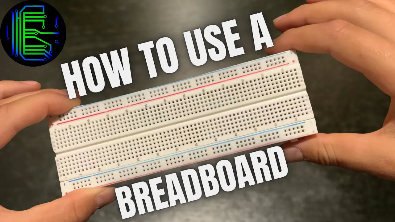
- Why this video: You must prototype circuit connections safely without soldering. This video visually outlines the internal electrical connections of standard breadboards, guiding you on how to distribute power and ground safely to mechanical actuators.
- Knowledge Checkpoint:
- Map out the internal metallic rails of a half-size breadboard (power buses vs. terminal strips).
- Create a simple LED circuit on a breadboard driven by a microcontroller's digital pins.
- Identify and prevent common electrical short circuits across the central divider.
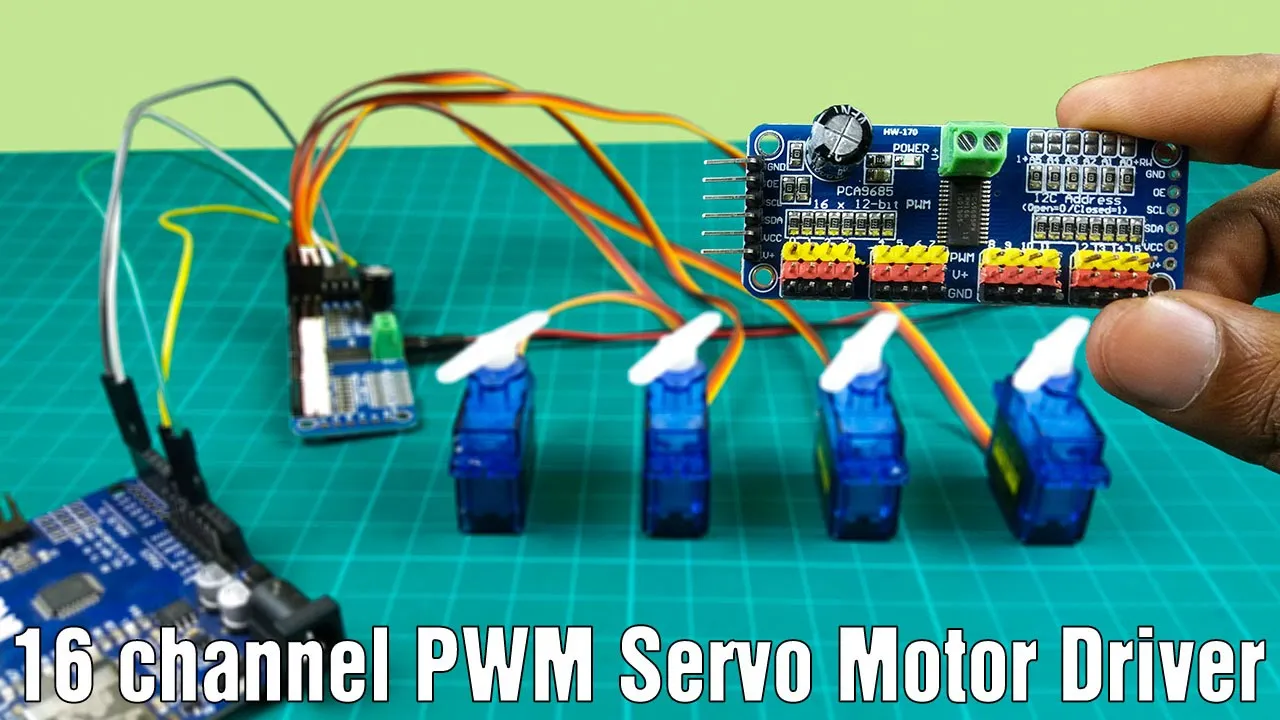
- Why this video: Standard microcontrollers lack the processing power and current capacity to drive multiple robotic joint servos simultaneously. This video covers the PCA9685 16-channel PWM driver board, demonstrating how to use I2C communication to offload PWM calculations and coordinate multi-axis movements with an external power source.
- Knowledge Checkpoint:
- Wire the PCA9685 driver to the Arduino using SDA/SCL (I2C) pins and an external 5V/6V power supply.
- Explain how PWM duty cycles correspond to exact angular positions (0 to 180 degrees) for hobby servos.
- Write a script using the Adafruit PWM Servo Driver library to sweep multiple connected servos to designated safe joint limits.
Module 2: CAD Design & Mechanical Assembly of a 3-Axis Arm
Designing a functional 3-axis robotic arm requires an understanding of structural engineering, joint configurations, and motor constraints. In this module, you will learn to navigate Autodesk Fusion 360 to construct solid models, define rotational constraints (revolute joints), run basic stress and assembly testing, and mathematically calculate the motor torque required to lift active payloads at maximum arm extension.
Recommended Videos

- Why this video: You cannot design a physical manipulator without understanding its kinematic boundaries. This video explains how mechanical joints (revolute, prismatic) restrict or enable motion, defining the total degrees of freedom (DOF) of your robot workspace.
- Knowledge Checkpoint:
- Calculate the DOF of a planar mechanism using Grubler’s formula.
- Distinguish between revolute joints and prismatic joints in terms of motion constraints.
- Map out the 3D workspace envelope of a 3-axis revolute configuration (anthropomorphic arm).
- Why this video: Real-world servos fail if their physical joint load exceeds their stall torque rating. This clip breaks down how mechanical leverage and gear ratios amplify or reduce required torque, providing a visual case study on torque calculation and linkage advantages.
- Knowledge Checkpoint:
- Calculate the torque required at a robot shoulder joint supporting a arm link of length and a end-effector payload.
- Explain how a gear ratio (e.g., 3:1) alters output torque and rotational velocity.
- Identify how physical linkages can distribute the weight of servos down to the static base to reduce load on distal joints.
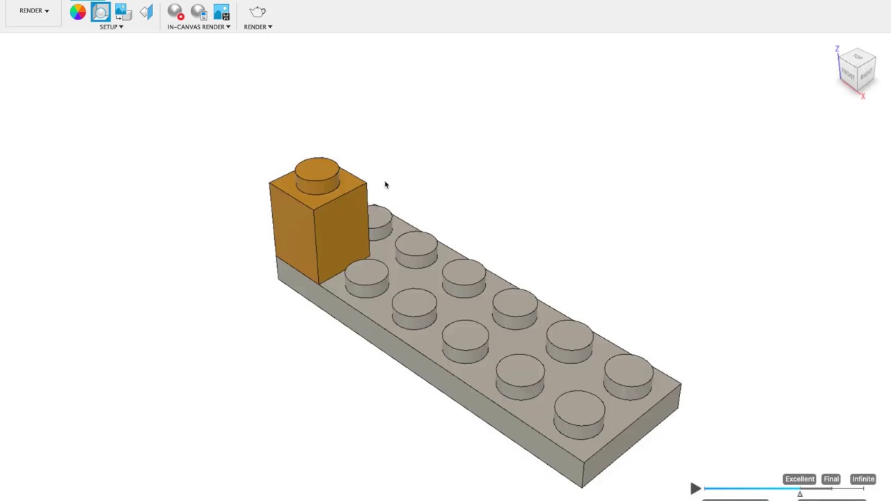
- Why this video: This video demonstrates assembly design in Autodesk Fusion 360. It teaches how to insert separate parts, establish component hierarchies, ground a static foundation base, and apply physical joints to ensure realistic movement boundaries.
- Knowledge Checkpoint:
- Ground the primary base of your robotic arm in Fusion 360 to prevent arbitrary floating in 3D space.
- Create a rigid group assembly for components that move as a single combined body.
- Apply revolute joints with specified angular limits (e.g., to ) to mimic physical servo limits.

- Why this video: A robotic arm requires a terminal mechanical end-effector to manipulate objects. This extensive tutorial walks through the construction of a dual-jaw robotic gripper, showing how to sketch, extrude, and model complex gear teeth configurations that mesh perfectly.
- Knowledge Checkpoint:
- Sketch and model an integrated gear and link design using projection and offset tools in CAD.
- Apply motion links between gears to ensure symmetrical closing and opening of gripper jaws.
- Prepare and export functional STL files optimized for 3D printing or fabrication.
Gap Note on CAD & Torque Calculations: High-quality videos detailing exact mathematical calculations for dynamic loads in multi-link robotic arms are rare. To calculate base/shoulder torque () at worst-case fully-extended static conditions, use: Always multiply the resulting stall torque requirement by a minimum factor of safety of to when selecting active hobby servo motors.
Module 3: Mathematics of Robotics: Forward & Inverse Kinematics
Kinematics forms the mathematical bridge between a target coordinate in physical space and the motor commands sent to a robot's joints. This module covers Forward Kinematics (FK)—calculating the tool-tip position from known joint angles —and Inverse Kinematics (IK)—deriving the unique joint angles required to reach a specific target coordinate. We will dissect geometric derivations using trigonometry, the Law of Cosines, and planar projections.
   Joint 2 (Elbow)
      o [θ2]
     / \
 L1 /   \ L2
   /     \
  o       o End-Effector (X, Y)
Joint 1 [Target Coordinate] (Shoulder)
Recommended Videos

- Why this video: This video contains the core mathematical derivation for this module. It walks through the geometric and algebraic derivation of 2-DOF and 3-DOF planar systems, transforming coordinate positions into trigonometric expressions that solve for joint angles.
- Knowledge Checkpoint:
- Derive (elbow angle) using the Law of Cosines based on link lengths , , and target distance.
- Explain how the "elbow up" and "elbow down" configurations represent dual algebraic solutions.
- Convert derived Cartesian coordinates into a planar subsystem to solve for (base joint rotation).
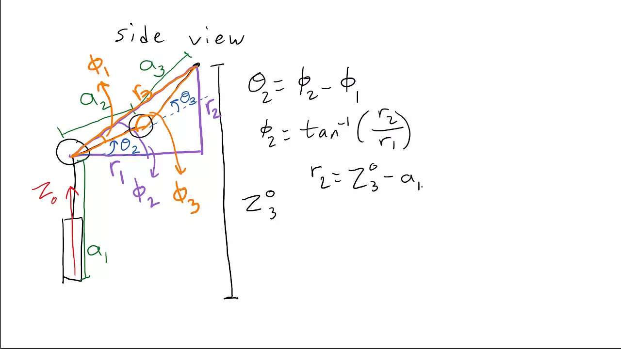
- Why this video: Real-world robotic arms operate in 3D, not just 2D planes. This video shows how to project a 3D articulated manipulator onto a 2D plane using planar right-triangles. Once projected, the 3D IK problem reduces to a simpler 2D coordinate solution.
- Knowledge Checkpoint:
- Isolate the azimuthal base angle () using the target coordinates and via the function.
- Define the radial distance in the horizontal plane as .
- Map the vertical coordinate and horizontal coordinate into a 2D vertical plane to solve for joint angles and .
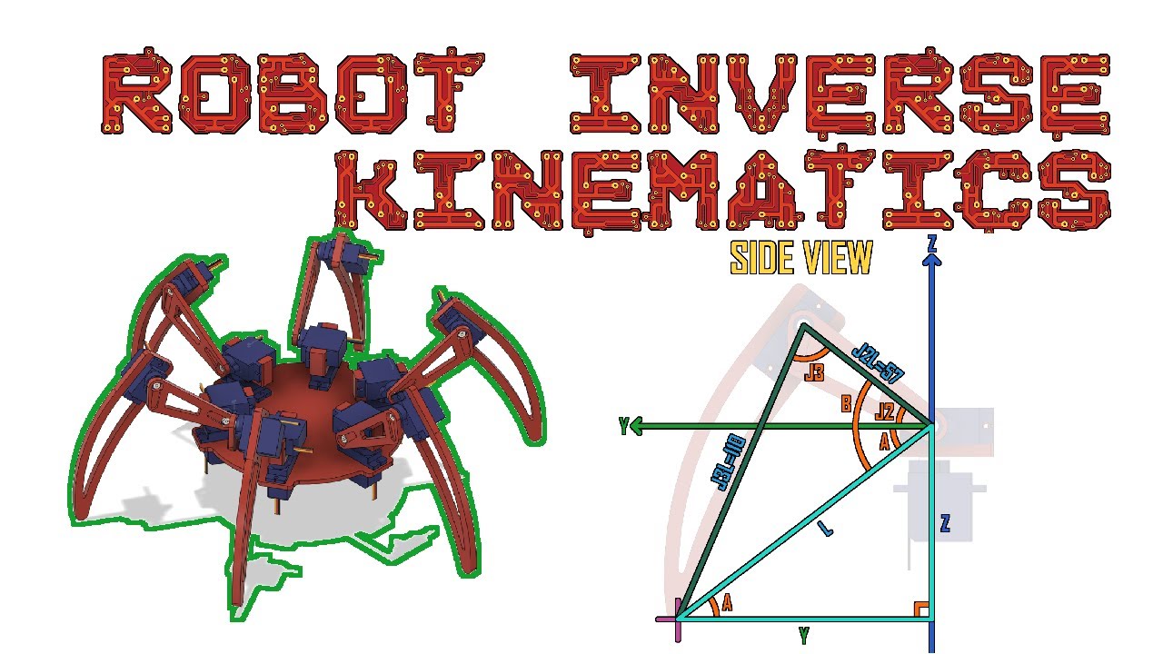
- Why this video: This video walks through the complete workflow of implementing derived trigonometric IK math into physical code. While demonstrating on a hexapod leg, the joints function as a 3-DOF serial chain identical to a 3-axis arm.
- Knowledge Checkpoint:
- Translate derived algebraic expressions into readable Python and C++ code using libraries like
math.h. - Handle domain errors when targeting coordinates outside the physical workspace boundary (e.g., values exceeding ).
- Code safety boundaries that automatically cap calculated angles before outputting to joint motors.
- Translate derived algebraic expressions into readable Python and C++ code using libraries like

- Why this video: This tutorial demonstrates how complex multi-link kinematics can be simplified into five straightforward lines of trigonometric operations. It provides a visual, intuitive explanation of geometric projections and relative angles.
- Knowledge Checkpoint:
- Identify the five essential lines of trigonometry required to program a standard 3-axis robot arm.
- Convert absolute joint angles relative to the horizon into relative angles required by adjacent motor linkages.
- Write a calibration program that tests accuracy by commanding the arm tip to trace a straight linear axis.
Module 4: Computer Vision with OpenCV for Object Detection
To enable autonomous sorting, your robot needs to "see". In this module, you will learn to implement computer vision algorithms using Python and OpenCV. We will explore camera streams, transform standard BGR color arrays into the robust Hue-Saturation-Value (HSV) space, filter target objects by color and shape, isolate contours, extract 2D pixel centroids, and understand the planar transformations needed to map camera frames onto a physical coordinate workspace.
Recommended Videos

- Why this video: This structured masterclass provides a deep dive into computer vision basics, covering installation, matrix manipulation, frame resizing, and threshold filtering. It serves as your comprehensive reference manual for the OpenCV framework.
- Knowledge Checkpoint:
- Set up an OpenCV python script to capture continuous frames from a live USB webcam feed.
- Explain how digital images are represented as multi-dimensional NumPy arrays of color channels.
- Write a script to convert raw image frames into grayscale and apply a Gaussian blur to reduce noise.
- Why this video: Computer vision engines struggle to track specific objects using basic Red-Green-Blue (RGB) profiles due to shadows and lighting fluctuations. This video demonstrates why and how to leverage Hue-Saturation-Value (HSV) space to isolate color boundaries reliably.
- Knowledge Checkpoint:
- Explain the parameters of HSV color space and why it outperforms BGR/RGB under changing illumination.
- Use OpenCV’s trackbars to dynamically isolate color profiles (e.g., bright blue sorting blocks) in real-time.
- Construct a binary mask to separate target object boundaries from background environments.
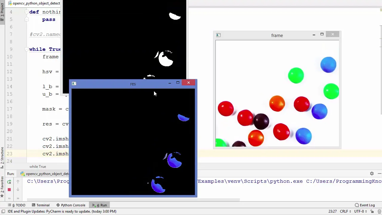
- Why this video: Once you've masked your target object, you need to extract its structural centroid. This video details how to chain HSV threshold masking with bitwise operations, contour detection, and centroid extraction.
- Knowledge Checkpoint:
- Apply binary thresholding and morphology operations (erosion, dilation) to clean up noise from a masked feed.
- Extract and draw bounding contours around detected objects.
- Use contour moments (
cv2.moments) to calculate the precise pixel centroid coordinate of a detected target block.

- Why this video: Your camera outputs pixel coordinates , but your physical robot arm moves in millimeter coordinates . This academic lecture by Peter Corke explains image projection geometry, lens distortions, and how planar homography transforms camera perspectives into physical flat coordinates.
- Knowledge Checkpoint:
- Explain how focal length and camera mounting heights introduce geometric perspective skewing.
- Define a homography transformation matrix and explain its utility in perspective correction.
- Map a skewed camera coordinate frame to a normalized rectangular workplane using reference markers.
Module 5: System Integration: Simulation and Automated Sorting
This final module integrates your hardware and software subsystems into a fully autonomous, closed-loop pick-and-place sorting robot. You will learn to perform empirical hand-eye calibration (mapping pixel coordinates directly to the robot's coordinates), establish robust serial communication protocols (via PySerial) to stream joint angles from Python to microcontrollers, program sequential state-machine logic for the sorting loop, and safely handle physical manipulation.
+------------------+ Pixel (U,V) +--------------------+ | Camera / OpenCV | ------------------> | Calibration Matrix | +------------------+ +--------------------+ | Workspace (X,Y) v +------------------+ Joint Angles +--------------------+ | Arduino Uno | <------------------ | IK Math Solver | | (PCA9685 Driver) | (PySerial) | (Python Workspace) | +------------------+ +--------------------+
Recommended Videos
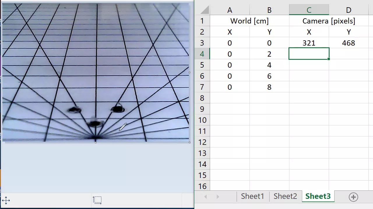
- Why this video: This video outlines how to run an empirical hand-eye calibration. It demonstrates how to collect matching coordinate pairs (pixel positions vs. corresponding physical robot touchpoints) and use second-order polynomial regressions to map camera coordinate pixels directly to physical space.
- Knowledge Checkpoint:
- Collect 4–8 calibration coordinate pairs matching known pixel values to physical arm coordinate extensions.
- Create mathematical mapping equations for both and dimensions based on pixel inputs.
- Write a mapping function that scales OpenCV centroids into physical millimeter coordinate targets.

- Why this video: This integration demo showcases the step-by-step physical coordinate conversion routine. It serves as a visual guide for configuring a camera looking down on a flat robotic sorting surface to drive pick-and-place routines.
- Knowledge Checkpoint:
- Set up an overhead workspace camera aligned with the coordinate axes of your physical robot base.
- Structure a software script that runs color tracking, triggers when an object is detected, and maps its coordinates.
- Formulate a sequence of moves (approach, descend, grasp, lift, transfer, release) to manipulate the targets.
- Why this video: For absolute pick accuracy, you must align the spatial origin of your optical sensor with the physical origin of your manipulator. This alignment demo walks through the mathematical transformation matrices needed to reconcile frame rotations and offsets.
- Knowledge Checkpoint:
- Define the rotational and translational offset matrix from the physical robot base center to your camera lens center.
- Transform derived target locations from the camera frame into coordinates relative to the base joint of your robot arm.
- Validate transformation accuracy by commanding the arm to track a visual target moved dynamically around the workspace.

- Why this video: This video demonstrates a successful end-to-end sorting implementation. It highlights color classification sorting (red, yellow, green, and blue targets) into dedicated regional bins, verifying that independent systems can work together smoothly.
- Knowledge Checkpoint:
- Program conditional branching paths (e.g., if target is Red, drop at position A; if Blue, drop at position B).
- Implement safety checks to verify that the robot arm returns to a home pose after completing a sorting operation.
- Optimize system parameters to complete a full sorting sequence (pick, sort, and return) in under 10 seconds.
Course Map
Below is the recommended sequence of modules. Notice how Module 1 (Foundations) and Module 2 (Mechanical Design) branch out independently before combining with mathematics and computer vision to culminate in the final integrated sorting system.
Key People Index
- Peter Corke (Professor of Robotic Vision): Developer of the Peter Corke Robotics Toolbox and author of foundational papers on robotic image geometry, camera parameters, and planar homography tracking. (Featured in Module 4).
- Daniel Shiffman (Educator, The Coding Train): Renowned computational artist and developer who popularized the visual simulation of multi-segmented forward and inverse kinematics using geometric constraints. (Referenced in Module 3 / IK frameworks).
- Murtaza Hassan (Murtaza's Workshop): Industry software engineer and specialized content developer who simplifies OpenCV workflows, microcontrollers, and Python implementations for practical, hands-on robotics. (Featured in Modules 1 & 4).
Final Self-Assessment
To verify you have mastered the core competencies of this curriculum, you should be able to check off every milestone in this comprehensive project checklist:
- Hardware Setup: Build a 3-axis physical or simulated mechanical arm assembly, securing the base and verifying that joint servos can move smoothly without physical collisions.
- Power Management: Connect an external 5V/6V DC power supply to a PCA9685 driver board to power the servos, ensuring the ground rails are shared with the microcontroller.
- Workspace Calibration: Manually actuate each physical joint to verify minimum and maximum limits, updating your software limits in Python/Arduino to prevent structural binding.
- Inverse Kinematics Derivation: Derive the geometric formulas for your 3-axis robot arm, transforming target coordinates into base, shoulder, and elbow joint angles.
- IK Solver Implementation: Write a Python function that runs your IK math in real-time, outputting joint angles while handling out-of-range coordinates cleanly.
- OpenCV Camera Stream: Set up a python script that reads frames from an overhead camera, applies a bilateral filter, and converts the feed into the HSV color space.
- Color & Shape Filtering: Configure an HSV color mask and contour detector that filters for sorting blocks by color (e.g., separating green blocks from red blocks).
- Centroid Extraction: Extract the pixel centroids of detected target blocks, ignoring noise smaller than a defined pixel-area threshold.
- Camera-to-Robot Mapping: Perform hand-eye calibration to establish a coordinate transformation matrix, converting pixel coordinates into physical workspace coordinates in millimeters.
- Serial Control Link: Program PySerial communication to package calculated joint angles into a robust payload (e.g.,
<angle1, angle2, angle3, gripper>) and stream it to the microcontroller. - Closed-Loop Integration: Build a master script that runs the entire loop: detect target block, transform coordinates, solve IK, move to approach, grasp, lift, deposit in the target bin, and return to home pose.