Underwater ROV: DIY Thrusters, ESCs & Video
Learning Goal: Construct and test a tethered underwater Remotely Operated Vehicle (ROV) featuring brushless thrusters, Electronic Speed Controllers (ESCs), and a live video feed for aquatic exploration.
- Prerequisites: Basic familiarity with Arduino programming, basic soldering, and hand tool safety.
- Estimated Total Study Time: 28 Hours
Module 1: Foundations of Underwater Robotics & Hydrodynamics
This module covers the core structural and physical challenges of operating a vehicle underwater. You will explore structural frame design, fluid dynamics, and Archimedes' principle.
Note on Pool Gaps: While the provided video pool features excellent structural PVC builds, it lacks formal academic lectures on fluid mechanics and Archimedes' principle. To master the physics of displacement and buoyancy forces, we highly recommend supplementing these videos with introductory physics literature on hydrostatic pressure () and Archimedes' principle ().
Recommended Videos
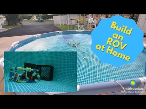
Why this video is valuable: This tutorial provides a practical, step-by-step introduction to choosing structural materials for an ROV. It highlights the differences between Schedule 40 (heavy, high-pressure rated) and thin-wall PVC pipes, which are preferred for weight-conscious, shallow-water DIY frames.
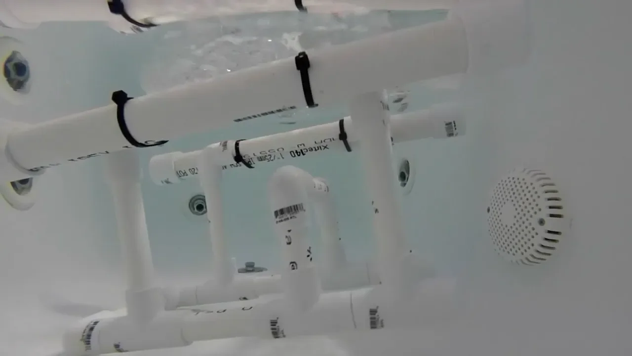
Why this video is valuable: This guide demonstrates the physical construction of a modular PVC ROV frame using various joint fittings (T-junctions, elbows). It explains how to make structural adjustments to the frame to prepare it for buoyancy modifications.
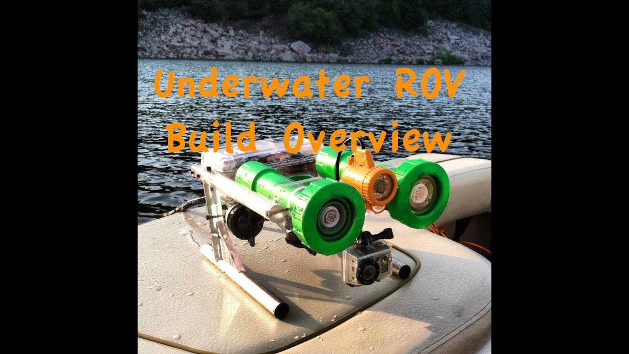
Why this video is valuable: This video provides a systems-level overview of a DIY ROV. It shows how structural frames, electronics enclosures, and thrusters integrate into a single functional machine. It also introduces the practical trade-offs between frame stability and component layout.
Knowledge Checkpoint
- Explain why thin-wall PVC is often preferred over Schedule 40 PVC for shallow-water DIY ROV frames.
- Calculate the buoyant force acting on a sealed 1-liter PVC cylinder fully submerged in fresh water ().
- Identify how the placement of heavy components (batteries, ballast) relative to flotation affects the vehicle's metacentric height and angular stability.
Module 2: Brushless Thrusters & Electronic Speed Controllers (ESCs)
Brushless DC (BLDC) motors offer outstanding power-to-weight ratios and reliability for underwater propulsion. This module explores how BLDC motors function, how ESCs drive them using six-step commutation, and how to program microcontrollers to send control signals.
Note on Pool Gaps: While standard outrunner BLDC motors can run underwater because their windings are typically insulated, the bearings will corrode over time if exposed to salt or fresh water without proper lubrication or sealing. To convert standard RC outrunners for marine use, research "brushless motor potting" and look up methods for packing motor bearings with marine grease.
Recommended Videos

Why this video is valuable: This short video explains why brushless motors are mechanically superior to brushed motors for wet environments: they lack physical commutator brushes that would quickly degrade or short-circuit in water.
Why this video is valuable: This video provides an in-depth look at Electronic Speed Controller (ESC) operations. It explains the six-step commutation process, showing how the ESC converts DC power into three-phase AC power to spin a brushless motor.
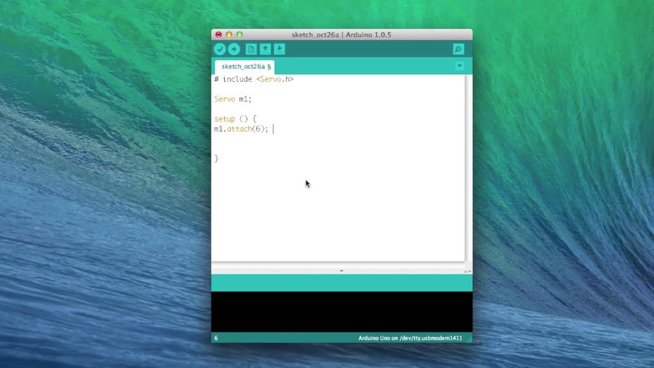
Why this video is valuable:
This practical coding guide shows how to interface an Arduino with a brushless ESC using the Servo library. It covers pin routing, initialization sequences, and the critical arming pulse needed to unlock the ESC at startup.
Why this video is valuable: This video demonstrates a real-world assembly of a waterproof brushless DC motor (Flipsky 3542) for underwater propulsion. It highlights initial spin testing and common troubleshooting steps for wet running.
Knowledge Checkpoint
- Explain the difference in water tolerance between brushed and brushless DC motors.
- Describe how six-step commutation works in a sensorless BLDC motor setup.
- Write a basic Arduino sketch that mounts a
Servoobject, sends a 1500-microsecond neutral arming signal, and takes input to sweep motor speed. - What precautions must be taken for standard steel motor bearings operated in wet environments?
Module 3: Waterproof Sealing, Enclosures & Hull Construction
Keeping electronics dry under pressure is the most difficult challenge in ROV engineering. This module teaches you how to design O-ring seals, calculate groove tolerances, build waterproof enclosures, and pot penetrations to prevent leaks.
Recommended Videos
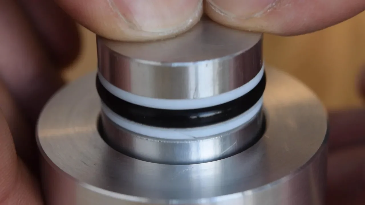
Why this video is valuable: This engineering animation explains how O-ring seals work, including the self-energizing mechanism where fluid pressure deforms the ring to create a tighter seal. It provides essential guidelines for gland dimensions and compression.

Why this video is valuable: This video shows how to make custom O-ring seals. It demonstrates how to cut O-ring cord to custom lengths and glue them into machined grooves. It also explains the rule of thumb for O-ring compression: squishing the ring to approximately 80% of its relaxed thickness.

Why this video is valuable: This field guide covers preparing and potting cable entries. It explains how to solvent-clean cables before applying potting compounds, ensuring the sealant bonds well to prevent water from wicking along the wires.
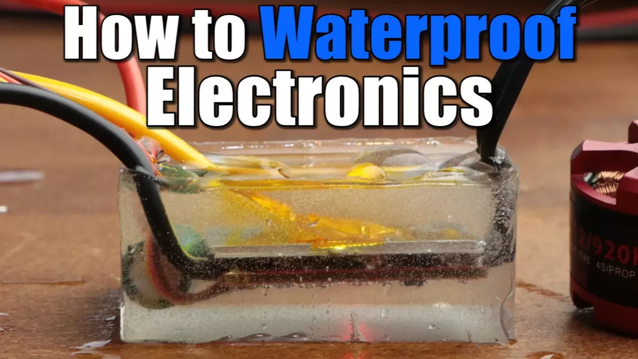
Why this video is valuable: This short video compares waterproofing methods like nail polish, silicone, and potting compound. It shows why potting compounds are highly effective for protecting sub-surface electronics like ESCs.
Knowledge Checkpoint
- Define "self-energizing" in the context of O-ring seals.
- If an O-ring has a cross-sectional diameter of 3.0 mm, calculate the target groove depth to achieve the recommended 20% compression (80% remaining height).
- Explain why wire wicking occurs and how proper potting surface preparation prevents it.
- Compare the mechanical strength and thermal properties of standard silicone versus marine potting epoxy.
Module 4: Power Distribution & Signal Control Electronics
Operating an ROV at the end of a long cable requires careful power management and reliable communication. This module covers voltage drop across long tethers, RS485 differential signaling, and joystick control systems.
Recommended Videos

Why this video is valuable: This video covers the physics of power transmission over long cables. It explains why transmitting power at a higher voltage (e.g., 48V) reduces current draw, which minimizes voltage drop and allows you to use thinner, lighter tether wires.
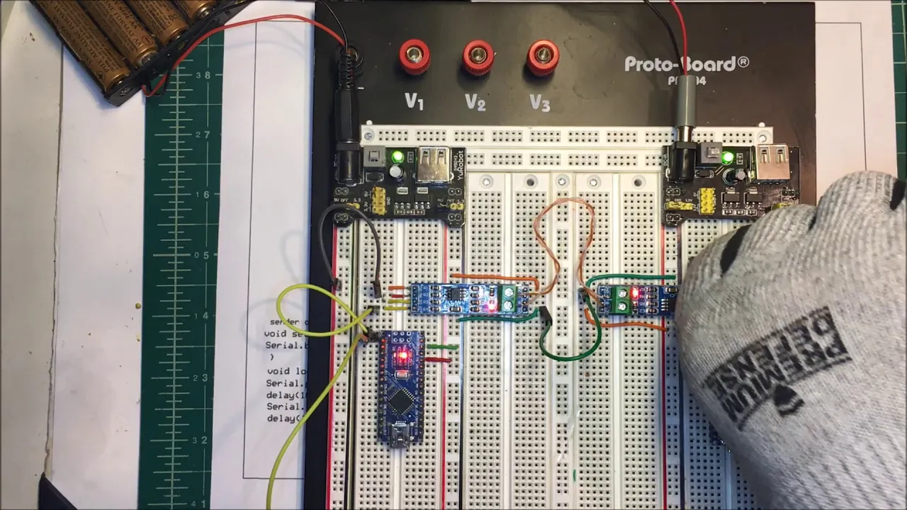
Why this video is valuable: Standard serial communication (TTL UART) degrades over long cables due to noise and resistance. This tutorial explains how to use MAX485 transceiver modules to convert signals to RS485. This protocol uses differential signaling to transmit data reliably over thousands of feet of tether.
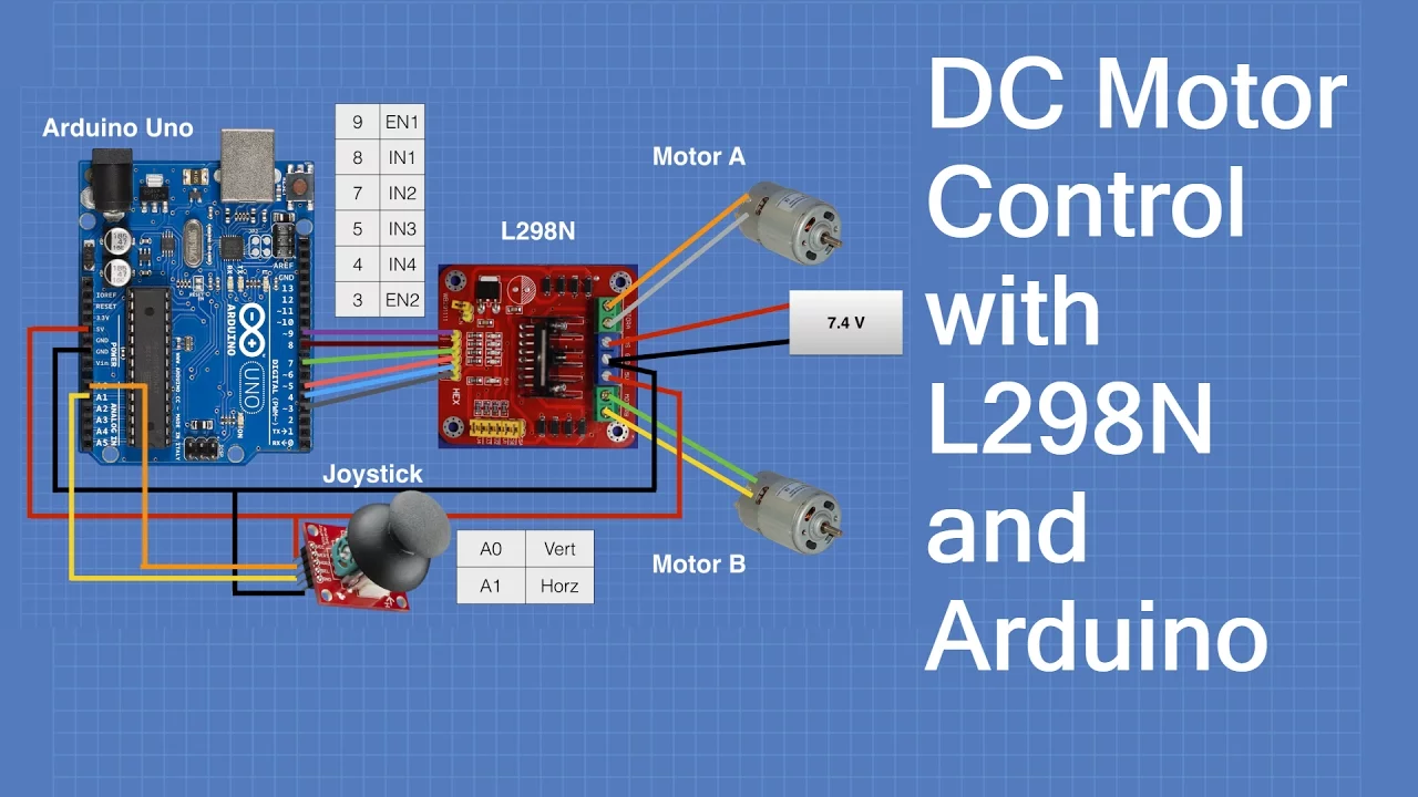
Why this video is valuable: This video explains how to read and map analog joystick signals. It shows how the joystick's internal potentiometers translate physical movement into dual-axis control signals for motor drivers.

Why this video is valuable: This build guide shows you how to wire and configure a multi-axis analog joystick. It is a helpful reference for constructing your topside control console.
Knowledge Checkpoint
- Using Ohm's Law (), calculate the voltage drop across a 100-foot copper tether (24 AWG, total loop resistance ) carrying a 3 Amp current.
- Explain how differential signaling in RS485 communication rejects external electromagnetic noise.
- Sketch the circuit schematic showing how to connect an Arduino Uno to a MAX485 breakout board.
- Map an analog joystick input pin (reading 0 to 1023) to scale to a standard servo control pulse (1000 to 2000 microseconds).
Module 5: Live Video Feed & Topside Communication
To navigate underwater, an ROV needs a low-latency live video feed. This module covers analog and digital video setups, camera options, and ground station control software.
Note on Pool Gaps: High-frequency digital signals, such as 5.8 GHz Wi-Fi or digital FPV, cannot travel through water. This is why underwater ROVs must send their video signals over a physical tether. Analog composite setups (using twisted pairs) offer zero-latency transmission over long tethers, while IP cameras can stream digital video using Ethernet-over-power or standard Ethernet lines.
Recommended Videos

Why this video is valuable: This video demonstrates how to set up a low-latency analog video system. It shows how to route a standard 700TVL analog camera's BNC composite output through a twisted-pair tether to a topside monitor.

Why this video is valuable: This clip explains the dual-camera configuration common in FPV systems. It distinguishes between the pilot's low-latency viewing feed and the high-definition footage recorded for later playback.
Why this video is valuable: This video introduces modern ground control station interfaces designed for sub-surface robotics. It explains how topside software receives video and telemetry feeds to display a unified pilot dashboard.
Why this video is valuable: This video demonstrates how to configure parameters in QGroundControl. While focused on drones, it explains the key steps for mapping controls and setting up communications, which are identical to configuring an ArduSub-powered ROV.
Knowledge Checkpoint
- Explain why FPV video signals cannot be transmitted wirelessly from a submerged ROV to a topside operator.
- Compare the advantages and disadvantages of an analog composite (NTSC/PAL) camera system with an digital IP camera system.
- What is the role of a ground control station (such as QGroundControl or Cockpit) in pilot communications?
- How do you map camera tilt controls alongside primary propulsion thrusters in a unified pilot interface?
Module 6: System Integration, Ballast Tuning & Pool Testing
This module covers final system integration. You will assemble your ROV, apply thread-locking compounds, perform ballast tuning to achieve neutral buoyancy, and run wet tests.
Recommended Videos
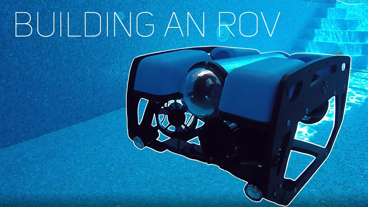
Why this video is valuable: This assembly guide covers the final steps of building an ROV. It covers organizing fastener hardware, mounting parts systematically, and using Loctite to prevent screws from vibrating loose under water.
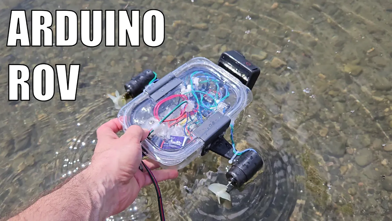
Why this video is valuable: This short video shows how to adjust an ROV's buoyancy. It explains how to combine ballast weights (to help it sink) and foam flotation (to keep it afloat) to achieve neutral buoyancy. This state allows the ROV to hover in the water column without wasting motor power.

Why this video is valuable: This training video shows how to adjust ballast weights to level an ROV. It explains how to place stainless steel weights so the vehicle sits perfectly flat and stable in the water.
Why this video is valuable: This documentary shows real-world sub-sea troubleshooting. It details how field crews identify and fix major system failures, such as earth faults and cable shorts, during deep-water deployments.
Knowledge Checkpoint
- Explain why thread-locking compounds (like Loctite) are critical for securing motor and frame mounts.
- Describe the physical state of "neutral buoyancy" and how to test for it in a pool environment.
- If your integrated ROV lists (tilts) to the starboard-aft corner during initial pool tests, explain where you should add flotation or remove ballast to level the vehicle.
- Detail the first three troubleshooting steps you would take if your topside monitor suddenly shows a loss of telemetry and video.
Course Map
Key People Index
- Nick Sopwith (Electrical Engineer & ROV builder): Known for his high-voltage, thin-wire power distribution designs and composite-over-twisted-pair analog video systems for amateur ROVs.
- The Tarkka Engineering Team: Fluid sealing educators who specialize in explaining self-energizing O-ring seal mechanisms and precision groove designs.
- Joshua Bardwell: A leading FPV drone educator whose tutorials on ArduPilot parameter configuration and joystick mapping apply directly to sub-surface vehicles.
Final Self-Assessment
Perform this comprehensive self-assessment to verify your readiness to build, submerge, and pilot your ROV:
- Frame Assessment: Your structural PVC frame is assembled, has drain holes to prevent trapped air pockets, and features a stable, low center of gravity.
- Propulsion Assessment: Brushless motors are securely mounted, and your ESCs are programmed with a startup arming routine.
- Waterproofing Assessment: Your main acrylic/PVC enclosure features dual O-ring seals with the correct 20% compression, and all cable entries are potted with marine epoxy.
- Power Assessment: Topside voltage and current values have been calculated to account for voltage drop across your tether, keeping your sub-surface DC-DC regulators within safe operating limits.
- Signal Assessment: Topside joystick inputs are successfully mapped through a MAX485 differential serial link, sending smooth motor commands down the tether.
- Video Assessment: The analog or digital camera feed displays on your topside screen with low enough latency for real-time navigation.
- Buoyancy Assessment: In a static test tank, your ROV floats level and achieves neutral buoyancy (it neither sinks nor floats when released).
- Safety Assessment: You have established a safety protocol, including emergency power-cut switches and motor-disable routines, to handle any system failures.